Challenge Your Soldering Skills With Snowy0201

From  on the Tindie blog:

Snowy0201_from_NWMaker_on_Tindie.jpg

The Snowy Owl is the rebel of owls. They live in the north near arctic regions of the world, and unlike other owls, they are active during the day instead of the night. Owls in general are pretty great, which is why this Snowy Owl version of the Surface Mount Device 0201 soldering challenge kit caught my eye.

For this challenge, the resistors on the back of the owl have been changed to a 0201 packages for an additional level of difficulty. These are cellphone-level miniaturization so it will be a challenge. A dual inverter NL27WZ04 is used to implement the ring oscillator, which drives the blinking LEDs.

Think you’re up to the challenge?


Challenge Your Soldering Skills With Snowy0201

USB-to-serial adapter board for Open Hardware Summit badge

This adapter board to connects a USB-to-serial cable to the 2018 Open Hardware Summit badge.

DpulizcW0AABn7E

The badge features an ESP32 microcontroller running MicroPython firmware.  The firmware provides a Python interpreter prompt (REPL) on the serial port which allows interactive programming of the badge!

DpuljnbW0AAb7st

A previous blog post describes how to build and flash new MicroPython firmware to the badge:


The KiCad design files are shared on GitHub:

oshwabadge2018/adapter-board

Screenshot from 2018-10-20 02-25-11.pngThe board has been shared on OSH Park:

OSH Park: adapter board for USB-to-serial cable

Screenshot from 2018-10-18 00-02-21

Order from OSH Park

Bill of Materials (BoM)

  • Switch for programming mode
    • E-Switch EG1218
    • Slide Switch SPDT
    • Digi-Key: EG1903-ND
  • Pushbutton for reset
    • Omron B3F-1000
    • Tactile Switch SPST-NO
    • Digi-Key: SW400-ND
  • Header for FTDI usb-to-serial cable
    • TE AMP 9-146282-0-06
    • 1×6 Pin Header 0.1″ pitch
    • Digi-Key: A34253-06-ND
  • Header to connect J1 socket on badge
    • Harwin M20-9720345
    • 2×3 Pin Header 0.1″ pitch
    • Digi-Key: 952-1921-ND
  • J1 header socket on the badge
    • Harwin 952-1781-ND
    • 2×3 Header Socket 0.1″ pitch
    • Digi-Key: M20-7830346

Digi-Key shopping cart

Screenshot from 2018-10-20 02-28-43

Resources:

USB-to-serial adapter board for Open Hardware Summit badge

Packing a Lot Into a Little PCB: Winners of the Square Inch Project on Hackaday

It is mind-boggling when you think about the computing power that fits in the palm of your hand these days. It wasn’t long ago when air-conditioned rooms with raised floors hosted computers far less powerful that filled the whole area. Miniaturization is certainly the order of the day. Things are getting smaller every day, too. We were so impressed with the minuscule entries from the first “Square Inch Project” — a contest challenging designers to use 1 inch2 of PCB or less — that we decided bring it back with the Return of the Square Inch Project. The rules really were simple: build something with a PCB that was a square inch.

via Packing a Lot Into a Little PCB: Winners of the Square Inch Project — Hackaday

Quote

Open Hardware Summit badge: accelerometer demo

IMG_20181016_084030

Want to use the KX122-1037 Accelerometer (datasheet) on the 2018 Open Hardware Summit badge?

Step 1:

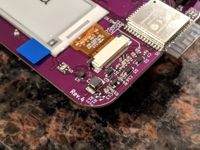
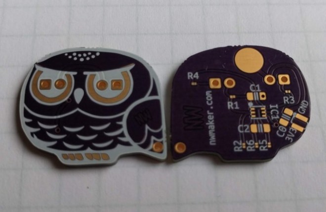
Make sure that R12 and R13 are populated.

IMG_20181004_202602 (1)

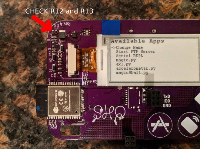
R12 and R13 are 2.2K Ohm resistors for the I2C bus.  This is needed for the accelerometer to work.  We mistakenly had DNP (do not place) on the BoM (Bill of Materials) for R12 and R13.

IMG_20181004_202414 (1)

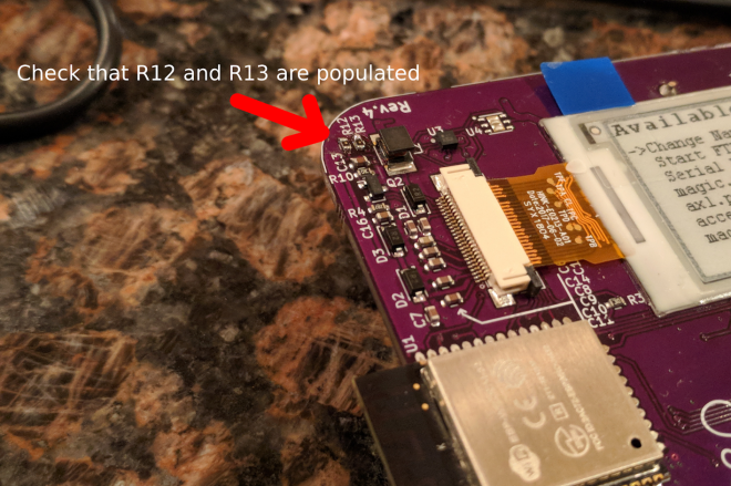
Awesome people at Artisan’s Asylum makerspace helped to solder these resistors on the badges right before Open Hardware Summit! 💜✨

It is possible that some badges were not reworked.  Please email [email protected] if they are missing from your badge.

This photo shows what is will look like when R12 and R13 are missing:

IMG_20181004_213549

Step 2:

Download the Python file named accelerometer.py from the ohs18apps repository on GitHub:Screenshot from 2018-10-17 23-35-18.png

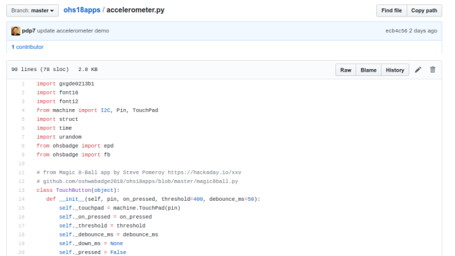
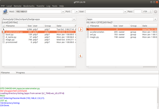
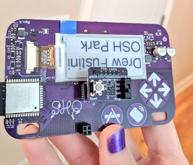
Start the FTP server and connect to the SSID listed on the badge:

Open your FTP client application and connect to 192.168.4.1:
Screenshot from 2018-10-03 23-58-59

After the transfer completes, power cycle the badge by removing the batteries and reinserting.

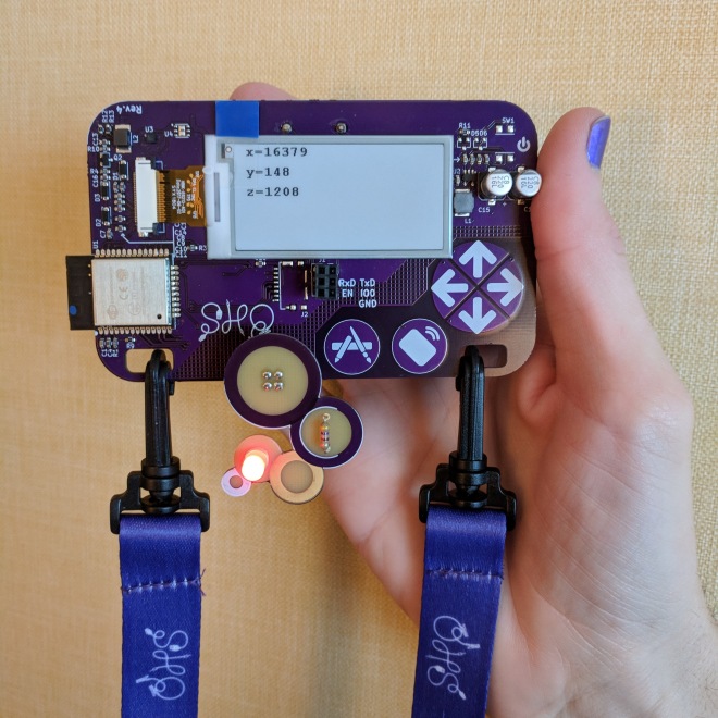
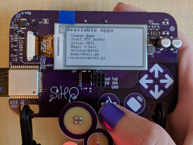
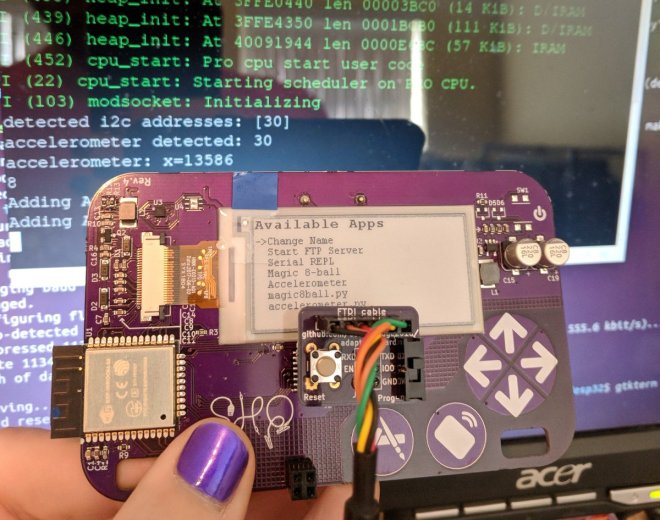
Press the left application button (with the paintbrush and pencil icons) to enter the menu.  accelerometer.py should then be listed under Available Apps menu.  Press the down cursor until accelerometer.py is selected and then press the application button again.

IMG_20181016_083924

Step 3:

The KX122-1037 Accelerometer datasheet describes the 3 different axis:

Screenshot from 2018-10-17 21-25-45

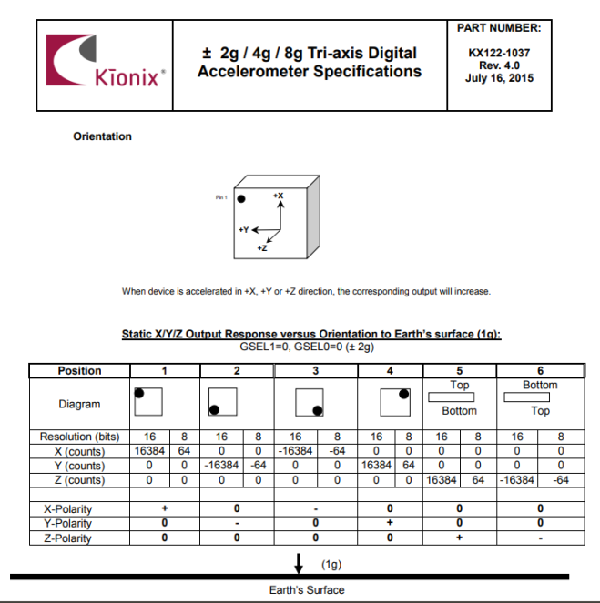
Here are examples of the X, Y and Z axis of the accelerometer for reference:

Resources:

Open Hardware Summit badge: accelerometer demo

Open House at Advanced Assembly on Oct. 25th

Screenshot from 2018-10-17 13-55-33.png

If you’re in the Denver area, come meet our new assembly partner: Advanced Assembly!

They’re having an open house:

Join us for pizza, beer and tours of our newly remodeled, high-tech facility as we celebrate 14 years in business. Bring your co-workers too!

Please RSVP

Screenshot from 2018-10-17 19-57-14.png

Open House at Advanced Assembly on Oct. 25th

Cool Tools: Deus Ex Autorouter

The first thing you probably asked yourself when learning how to lay out PCBs was “can’t the computer do this?” which inevitably led to the phrase “never trust the autorouter!”. Even if it hooks up a few traces the result will probably be strange to human eyes; not a design you’d want to use.

But what if the autorouter was better? What if it was so far removed from the autorouter you know that it was something else? That’s the technology that JITX provides. JITX is a company that has developed new tools that can translate a coarse textual specification of a board to KiCAD outputs autonomously.

How do you use JITX? At this point the company provides a front end to their tools; you use their website contact form to talk to a human (we assume) about what you want to make and how. But watching their demo videos (see the bottom of this post) gives a hint about how the tooling actually works. In brief; it takes a specification in a domain specific language that describes the components to use, then compiles (synthesizes?) that into KiCAD files that can be sent to fab.

via Cool Tools: Deus Ex Autorouter — Hackaday

Quote

The Incredible Judges Of The Hackaday Prize

The last challenge of The Hackaday Prize has ended. Over the past few months, we’ve gotten a sneak peek at over a thousand amazing projects, from Open Hardware to Human Computer Interfaces. This is a contest, though, and to decide the winner, we’re tapping some of the greats in the hardware world to judge these astonishing projects.

Below are just a preview of the judges in this year’s Hackaday Prize. In the next few weeks, we’ll be sending the judging sheets out to them, tallying the results, and in just under a month we’ll be announcing the winners of the Hackaday Prize at the Hackaday Superconference in Pasadena. This is not an event to be missed — not only are we going to hear some fantastic technical talks from the hardware greats, but we’re also going to see who will walk away with the Grand Prize of $50,000.

via The Incredible Judges Of The Hackaday Prize — Hackaday

Quote

Creating a DIP ATtiny85 Watch with the DS3231

Untitled drawing

Creating a DIP ATtiny85 Watch with the DS3231

As Douglas Adams explained in The Hitchhiker’s Guide to the Galaxy, digital watches are “pretty neat” to us primitive life forms. Something about the marriage of practicality, and sheer nerdiness gets me oddly excited. Somewhere in my fascination I asked myself, “can I make a digital watch entirely of my design?” I did! And it taught me a lot about pcb fabrication, low power programming, and shift registers.

ezgif.com-crop

Probably the most important function of a watch is that it keeps time. While you could use your microcontroller to count the seconds and save on parts, there are some major downsides to this. For one, the microcontroller is much worse at keeping time than a dedicated RTC (Real Time Clock) IC, the time would drift significantly with temperature and battery voltage. Another serious problem is that it would require the microcontroller to always be on, keeping track of the time. This would consume much more current than an RTC IC, draining the battery significantly faster. Thus we employ a DS3231 to casually sit in the background, consuming microamps from it’s own back-up battery (which, at the rate of 200µA, would take 12.56 years to drain).

Creating a DIP ATtiny85 Watch with the DS3231