Hackaday: Retro Recreations Hack Chat with Eric of Tube Time

Join Hackaday on Wednesday, March 17 at noon Pacific for the Retro Recreations Hack Chat with Eric of TubeTimeUS:

join-hack-chat

Nostalgia seems to be an inevitable consequence of progress. Advance any field far enough into the future, and eventually someone will look back with misty eyes and fond memories of the good old days and start the process of turning what would qualify as junk under normal conditions into highly desirable collectibles.

In some ways, those who have been bitten by the computer nostalgia bug are lucky, since the sheer number of artifacts produced during their period of interest is likely to be pretty high, making getting gear to lovingly restore relatively easy. But even products produced in their millions can eventually get difficult to find, especially once they get snapped up by eager collectors, leaving the rest to make do or do without.

Of course, if you’re as resourceful as Tube Time is, there’s another alternative: build your own retro recreations. He has embarked on some pretty intense builds to recapture a little of what early computer enthusiasts went through trying to build useful machines. He has built replicas of early PC sound cards, like an ISA-bus AdLib card, its MCA equivalent, and the “Snark Barker”— or is it the “Snood Bloober”? — which bears an uncanny resemblance to the classic Sound Blaster card from the 1980s.

Tube Time will join us for the Hack Chat this week to answer questions about all his retro recreations, including his newest work on a retro video card. Be sure to bring your questions on retro rebuilds, reverse engineering, and general computer nostalgia to the chat.

Our Hack Chats are live community events in the Hackaday.io Hack Chat group messaging. This week we’ll be sitting down on Wednesday, March 17 at 12:00 PM Pacific time. If time zones have you tied up, we have a handy time zone converter.

Hackaday: Retro Recreations Hack Chat with Eric of Tube Time

Simultaneous Soldering Station

https://hackaday.io/project/171848-soldering-rt1

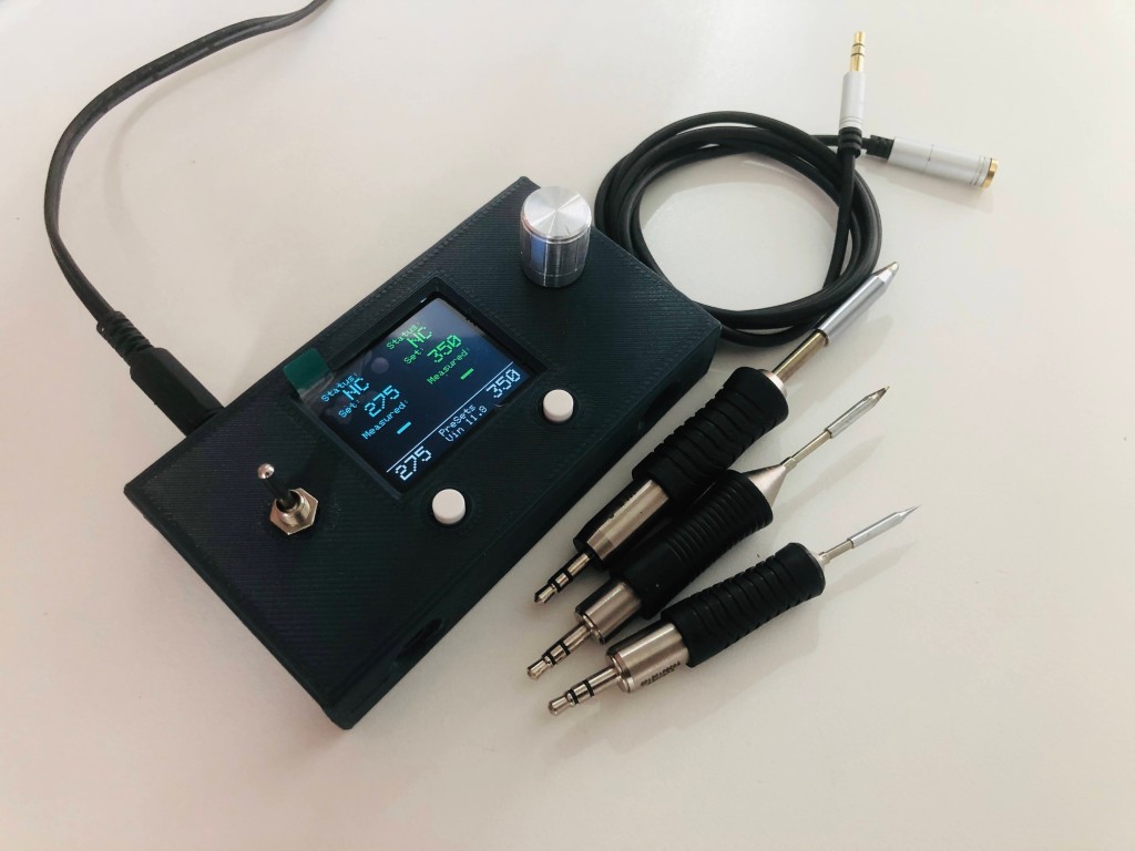
Soldering irons are a personal tool. Some folks need them on the cool side, and some like it hot. Getting it right takes some practice and experience, but when you find a tip and temp that works, you stick with it. [Riccardo Pittini] landed somewhere in the middle with his open-source soldering station, Soldering RT1. When you start it up, it asks what temperature you want, and it heats up. Easy-peasy. When you are ready to get fancy, you can plug in a second iron, run off a car battery, record preset temperatures, limit your duty-cycle, and open a serial connection.

The controller has an Arduino bootloader on a 32u4 processor, so it looks like a ProMicro to your computer. The system works with the RT series of Weller tips, which have a comprehensive lineup. [Riccardo] also recreated SMD tweezers, and you can find everything at his Tindie store.

Soldering has a way of bringing out opinions from novices to masters. If we could interview our younger selves, we’d have a few nuggets of wisdom for those know-it-alls. If ergonomics are your priority, check out TS100 3D-printed cases, which is an excellent iron, in our opinion.

Read more: Simultaneous Soldering Station — Hackaday

Simultaneous Soldering Station

Handheld Apple IIe emulator powered by Teensy

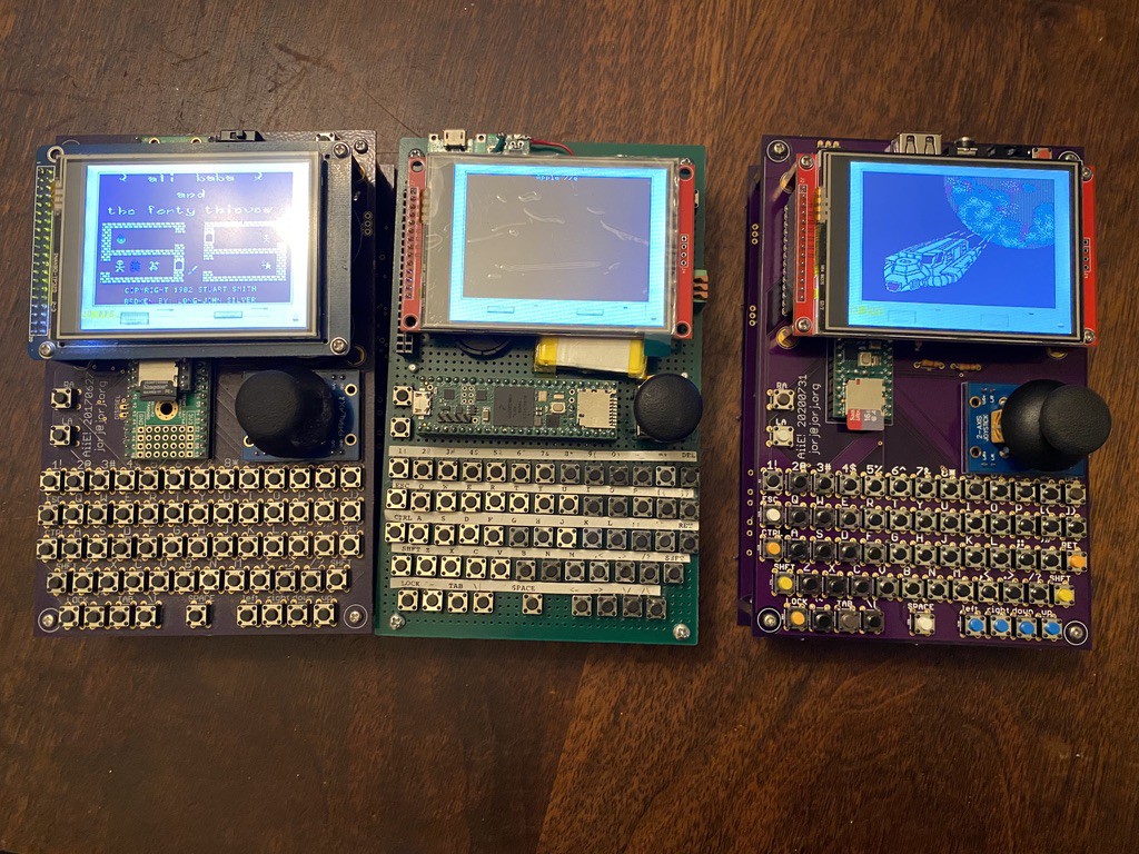
Jorj Bauer has created a handheld Apple IIe emulator with a Teensy:

Aiie! – an embedded Apple //e emulator

Teensy 4.1 (600 MHz arm Cortex M7) running a full-speed Apple //e emulator. Because everyone needs one of these, right?

The OSH Park boards arrived, and I spent some time Monday assembling! Here’s a time lapse of the build, which took me shy of 3 hours (mostly because I hadn’t organized any of the parts and had to hunt for several).

Handheld Apple IIe emulator powered by Teensy

Stepper Motor FeatherWing

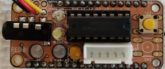
Lex Kravitz has designed a simple board containing the ULN2003 stepper motor driver in a Feather form factor:

Screenshot from 2020-08-02 11-31-59

Feather ULN2003 Stepper Wing

This Feather Wing was made to be hand assembled with through-hole components, which I find easier to put together in small runs.  In the future I may make a version with SMD components as well for professional manufacture.  I made this to control 5V 28BYJ-48 steppers that are easily available for ~$2-3 each.  Often they come with a ULN2003 driver board, if you are thrifty you can grab the chip off the board and move it to this board saving ~50 cents per board.

This board contains:

1) Two 3-pin headers (GND, PWR, and SIG).  These can be used to control a servo or additional sensor.

2) A 3.5mm TRRS port for external control

3) Two LEDs tied to digital pins

4) The ULN2003 motor driver

5) Two small buttons for user control

Stepper Motor FeatherWing

Agricoltura: connected control system for agriculture

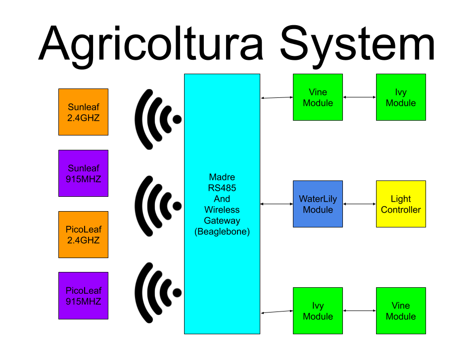
Adam Vadala-Roth has posted on Hackaday.io about a connected control system for all agriculture applications based on RS485 control nodes and multiple wireless sensor networks:

8246911593228843731

Agricoltura

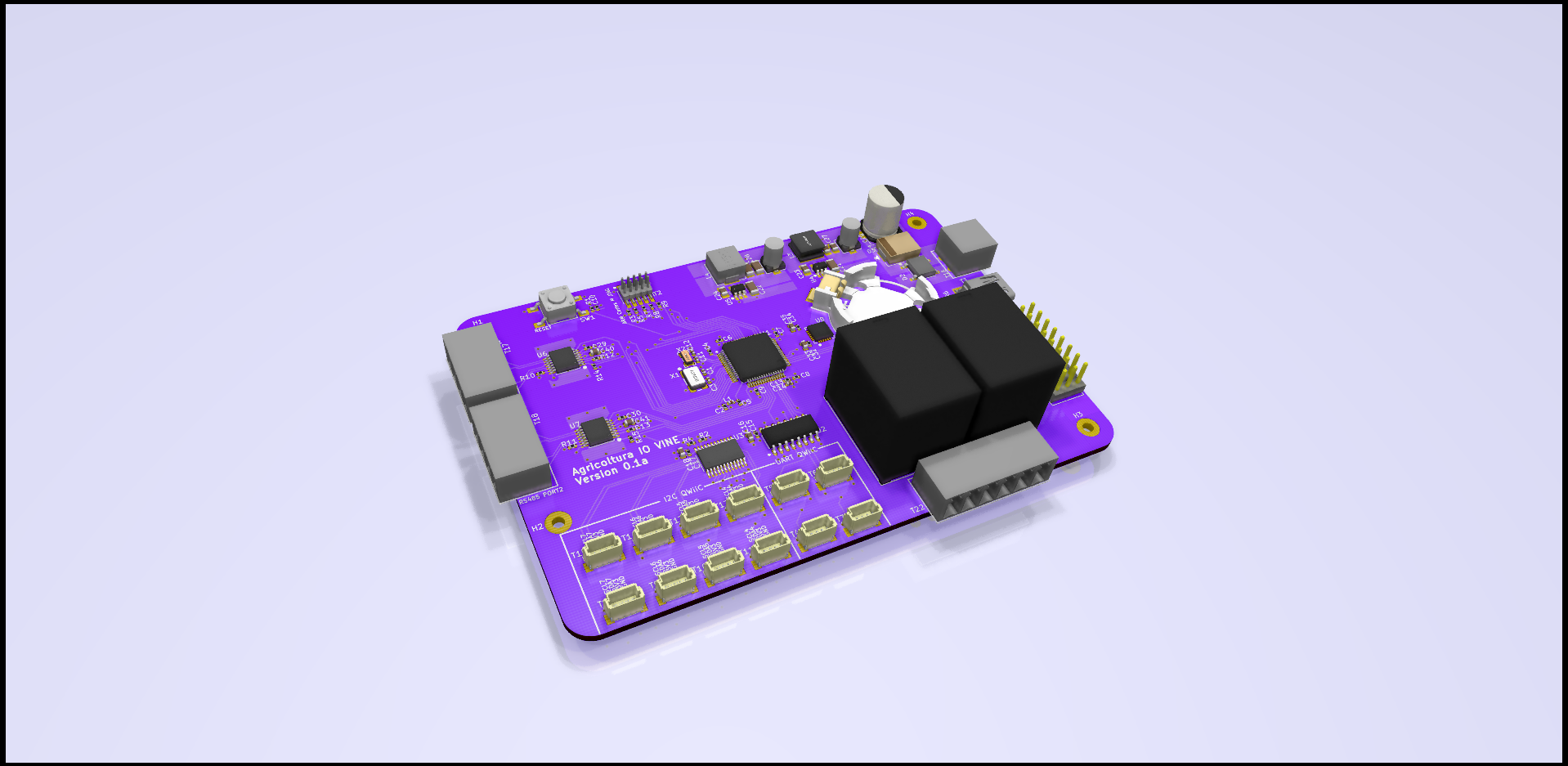
Agricoltura is the culmination of multiple projects I’ve worked on in the past related to the sensing and control of agriculture systems, notably HydroPWNics and SunLeaf.  Agricoltura aims to unite all the concepts of those past projects into a new system based primarily on RS485 nodes for control of pumps, sensor sampling, and light control.

The base system will be a gateway controller linked to daisy chainable RS485 nodes designed for specific functions. These nodes are built around a board called Vine.
Vine allows interfacing of QWIIC connect sensros and devices as well as relay control. Coming in as two varients Vine can be used to setup and control complete hydroponic farming systems or any other agriculture system.

4070251593134247670


Agricoltura: connected control system for agriculture

Breakout board for 8×12 analog cross-point switch

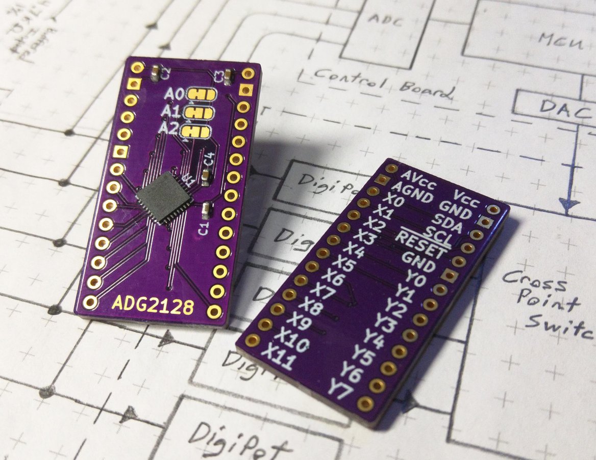
J. Ian Lindsay of  Manuvr Breakouts has designed this breakout board for Analog Devices’ 8×12 analog cross-point switch:

2019-12-01T08_58_25.068Z-IMG_20191201_013632

ADG2128 Breakout

The ADG2128 is an incredibly flexible cross-point switch. It supports 5/-5v, 3.4MHz i2c, and is unrestricted as to its connectivity options between its rows and columns.

This is a high-dollar part, and I’ve been designing with it for more than 5 years. So I polished my breakout board to reuse them during a project’s prototyping phase.

This board has decoupling capacitors adequate to handle the whole analog voltage range, i2c address selection jumpers, and differentiated ground layers for noise isolation or differential operation below 0v, according to the project’s demands.


Breakout board for 8×12 analog cross-point switch

ESP32-S2 Hack Chat with Adafruit on Hackaday

AdafruitESP32HackChatPosterV1_1-01

Join us on Wednesday, May 6 at noon Pacific for the ESP32-S2 Hack Chat with Limor “Ladyada” Fried and Scott Shawcroft!

When Espressif released the ESP8266 microcontroller back in 2014, nobody could have predicted how successful the chip was to become. While it was aimed squarely at the nascent IoT market and found its way into hundreds of consumer devices like smart light bulbs, hackers latched onto the chip and the development boards it begat with gusto, thanks to its powerful microcontroller, WiFi, and lots of GPIO.

The ESP8266 was not without its problems, though, and security was always one of them. The ESP32, released in 2016, addressed some of these concerns. The new chip added another CPU core, a co-processor, Bluetooth support, more GPIO, Ethernet, CAN, more and better ADCs, a pair of DACs, and a host of other features that made it the darling of the hacker world.

Now, after being announced in September of 2019, the ESP32-S2 is finally making it into hobbyist’s hands. On the face of it, the S2 seems less capable, with a single core and neither Bluetooth nor Ethernet. But with a much faster CPU, scads more GPIO, more ADCs, a RISC-V co-processor, native USB, and the promise of very low current draw, it could be that the ESP32-S2 proves to be even more popular with hobbyists as it becomes established.

To talk us through the new chip’s potential, Limor “Ladyada” Fried and Scott Shawcroft, both of Adafruit Industries, will join us on the Hack Chat. Come along and learn everything you need to know about the ESP32-S2, and how to put it to work for you.

join-hack-chatOur Hack Chats are live community events in the Hackaday.io Hack Chat group messaging. This week we’ll be sitting down on Wednesday, May 6 at 12:00 PM Pacific time. If time zones have got you down, we have a handy time zone converter.

Click that speech bubble to the right, and you’ll be taken directly to the Hack Chat group on Hackaday.io. You don’t have to wait until Wednesday; join whenever you want and you can see what the community is talking about.

via ESP32-S2 Hack Chat with Adafruit — Hackaday

Quote

Fetch: World’s Largest Open-Source Ferrofluid Display

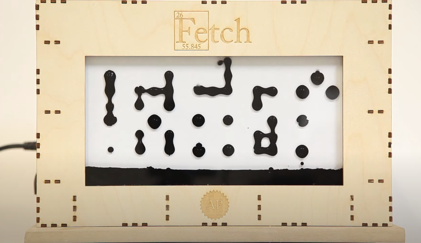
Applied Procrastination has created a 252 electromagnet-matrix that controls ferrofluid:

Screenshot from 2020-04-20 16-42-09

Fetch: A Ferrofluid Display

A student-project at the University of Oslo. We have designed and built a massive ferrofluid-display with 252 electromagnetic “pixels”. The display has a 12×21 resolution (the closest we could get to 16:9 on our budget), and is not DONE.

On Applied Procrastination we’ve shared all the details of this project and hope that it will inspire you to make something similar – or follow your own dream projects.

https://www.youtube.com/watch?v=5PFgVtzsXHM

Fetch: World’s Largest Open-Source Ferrofluid Display

“No knobs! No 555s! No reason whatsoever!”

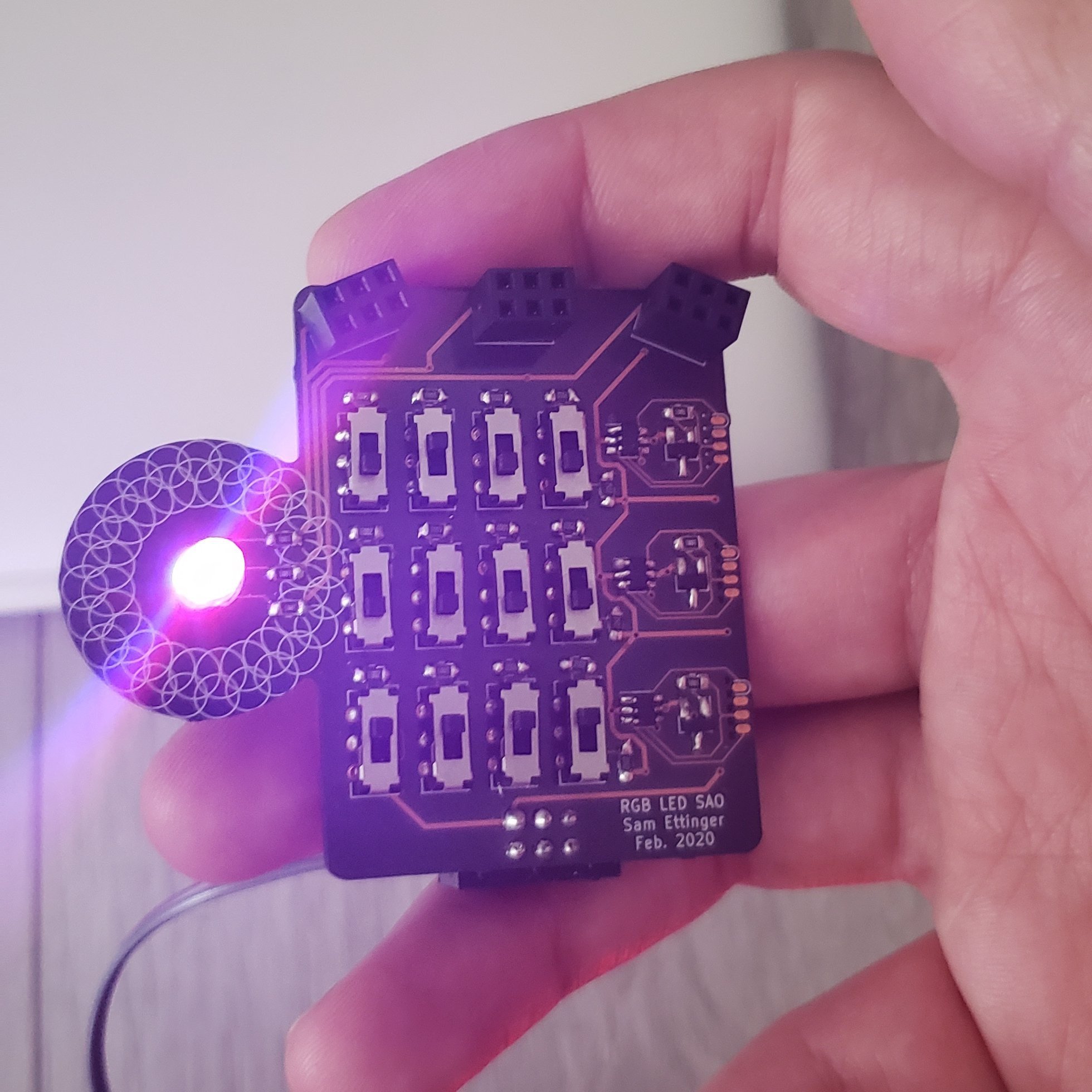
Here’s a #badgelife project from Sam Ettinger on Hackaday.io:
EVO_Vn_UwAA_eAt

This is a shitty add-on with one RGB LED controlled by twelve switches. The top row controls the red brightness, the middle row controls the green brightness, the bottom row the blue brightness. Each row of switches is like a 4-bit binary number, giving 16 brightness options for each color channel.

Should I have used knobs instead of switches? Maybe, but then it’s not a shitty add-on, is it?

Each color channel is controlled by its own ATtiny10, reading an analog voltage and PWMing the LED accordingly. The ATtiny10s are programmed using [Simon Merrett]’s SOICbite footprint, which I *love*.

Should I have used a 555 instead of a microcontroller? Perhaps. But isn’t this a better solution for a shitty add-on?

“No knobs! No 555s! No reason whatsoever!”

Low Power ESP32 Handheld

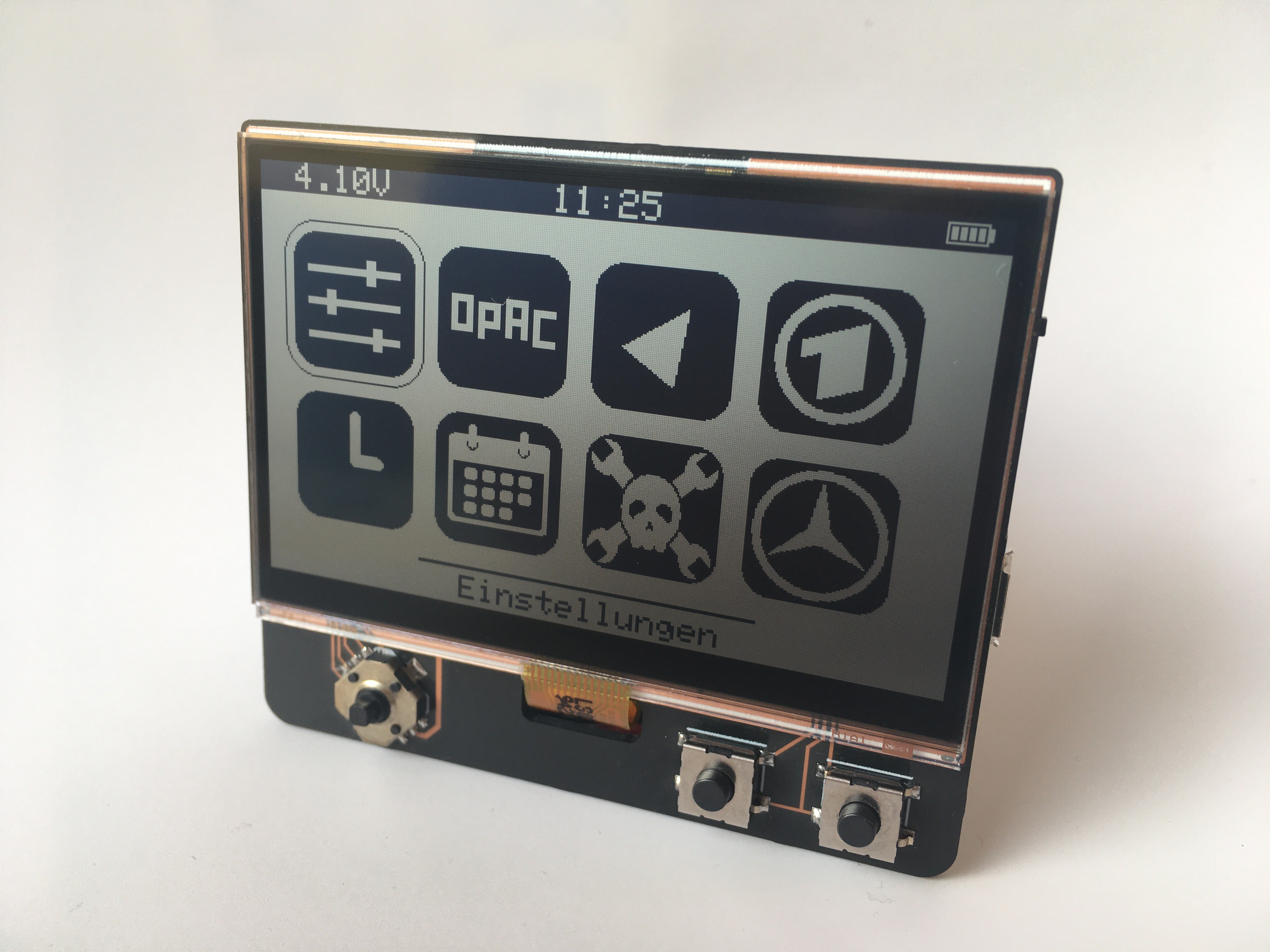
Max.K on Hackaday.io has created a pocket sized ESP32 display board with 300µW Always On Display:

7327171577179362033.jpeg

Low Power ESP32 Handheld

This handheld board is powered by an ESP32 and features a transflective Sharp memory LCD.  Similar to my previous Chronio smartwatch the focus of this project is on low power consumption.  Using the ESP32’s ULP core, the board can go into deep sleep with an active display.   The software includes a menu interface with a simple RSS reader.

Some of the key features are:
– 400x240px 2.7″ SHARP memory display
– 350 mAh LiPo battery with USB charging
– Always On Display with 300 µW power consumption
– 4-way joystick and buttons
– Date and time using built in RTC with NTP sync
– RSS Feed / Website parser

Layout files and Code on GitHub: https://github.com/CoretechR/ESP32-Handheld


Low Power ESP32 Handheld