Join us on Wednesday, May 6 at noon Pacific for the ESP32-S2 Hack Chat with Limor “Ladyada” Fried and Scott Shawcroft!
When Espressif released the ESP8266 microcontroller back in 2014, nobody could have predicted how successful the chip was to become. While it was aimed squarely at the nascent IoT market and found its way into hundreds of consumer devices like smart light bulbs, hackers latched onto the chip and the development boards it begat with gusto, thanks to its powerful microcontroller, WiFi, and lots of GPIO.
The ESP8266 was not without its problems, though, and security was always one of them. The ESP32, released in 2016, addressed some of these concerns. The new chip added another CPU core, a co-processor, Bluetooth support, more GPIO, Ethernet, CAN, more and better ADCs, a pair of DACs, and a host of other features that made it the darling of the hacker world.
Now, after being announced in September of 2019, the ESP32-S2 is finally making it into hobbyist’s hands. On the face of it, the S2 seems less capable, with a single core and neither Bluetooth nor Ethernet. But with a much faster CPU, scads more GPIO, more ADCs, a RISC-V co-processor, native USB, and the promise of very low current draw, it could be that the ESP32-S2 proves to be even more popular with hobbyists as it becomes established.
To talk us through the new chip’s potential, Limor “Ladyada” Fried and Scott Shawcroft, both of Adafruit Industries, will join us on the Hack Chat. Come along and learn everything you need to know about the ESP32-S2, and how to put it to work for you.
Our Hack Chats are live community events in the Hackaday.io Hack Chat group messaging. This week we’ll be sitting down on Wednesday, May 6 at 12:00 PM Pacific time. If time zones have got you down, we have a handy time zone converter.
Click that speech bubble to the right, and you’ll be taken directly to the Hack Chat group on Hackaday.io. You don’t have to wait until Wednesday; join whenever you want and you can see what the community is talking about.
adafruit
Adafruit becomes the company with the most certified OSHW
Exciting news from Adafruit:

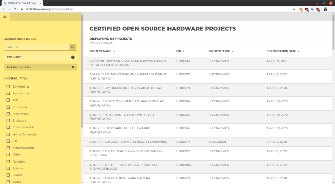
Adafruit has become the #1 most OSHWA certified open-source hardware company
Yesterday, April 20th, Adafruit became the #1 most OSHWA certified open-source hardware company. In the last 27 days, 387 boards have been submitted by Adafruit for review by the Open Source Hardware Association (OSHWA). Of those 387 boards, 54 have already been approved. There are around 6 boards left to be submitted, which should bring the number of approved Adafruit boards to around 393.
View the the full list of the certified boards:
Find out more about the Open Source Hardware Association (OSHWA) and their certification process.
Adafruit submitting OSHW certifications for boards
Exciting news from the Adafruit team, they have started the Open Source Hardware certification process for a bunch of their boards:
Adafruit submitting OSHW certifications for boards
Adafruit is an Open Source Hardware and Software company. To that end, Adafruit has begun working to submit many of their boards for certification by the Open Source Hardware Association. According to OSHWA:
“The certification program exists to make it easy for creators and users to identify hardware that follows the community definition of open source hardware maintained by OSHWA. Hardware projects that display the certification logo are licensed and documented in a way that makes it easy for users to use and build upon them.”
By registering their boards with OSHWA, Adafruit aims to ensure users that the products they sell are open-source, and easy to learn about.
Here are the boards that have recently been submitted:
CircuitPython Boards
- Adafruit Feather M0 Basic Proto
- Adafruit Feather M0 Adalogger
- Adafruit Metro M4
- Adafruit Feather M0 Express
- Adafruit Feather nRF52832 Bluefruit LE
- Adafruit Trinket M0
- Adafruit GEMMA M0
- Adafruit ItsyBitsy M0 Express
- Adafruit ItsyBitsy M4 Express
- Adafruit Feather M4 Express
- Adafruit HalloWing M0 Express
- Adafruit NeoTrellis M4 Mainboard
- Adafruit Metro M4 Express AirLift
- Adafruit Feather nRF52840 Express
- Adafruit Grand Central M4 Express
- Adafruit PyPortal
- Adafruit PyBadge
- Adafruit PyGamer
- Adafruit PyRuler
- Adafruit EdgeBadge
- Adafruit PyPortal Titano
- Adafruit PyPortal Pynt
- Adafruit ItsyBitsy nRF52840 Express
- Adafruit CLUE
- Adafruit Feather nRF52840 Sense
FeatherWings
- Adafruit FeatherWing OLED – 128×32 OLED Add-on For Feather
- Adalogger FeatherWing – RTC + SD Add-on For All Feather Boards
- DC Motor + Stepper FeatherWing Add-on For All Feather Boards
- 8-Channel PWM or Servo FeatherWing Add-on For All Feather Boards
- NeoPixel FeatherWing – 4×8 RGB LED Add-on For All Feather Boards
- Adafruit 4-Digit 7-Segment LED Matrix Display FeatherWing
- Adafruit 14-Segment Alphanumeric LED FeatherWing
- Adafruit Ultimate GPS FeatherWing
- Adafruit 15×7 CharliePlex LED Matrix FeatherWing
- TFT FeatherWing – 2.4″ 320×240 Touchscreen For All Feathers
- Adafruit Mini Color TFT with Joystick FeatherWing
- Adafruit CRICKIT FeatherWing for any Feather
- Adafruit AMG8833 IR Thermal Camera FeatherWing
- Adafruit INA219 FeatherWing
- Adafruit TFT FeatherWing – 3.5″ 480×320 Touchscreen for Feathers
- Adafruit Prop-Maker FeatherWing
- Adafruit 2.13″ Tri-Color eInk / ePaper Display FeatherWing
- Adafruit ADXL343 + ADT7410 Sensor FeatherWing
- Adafruit 2.13″ Monochrome eInk / ePaper Display FeatherWing
- Adafruit AirLift FeatherWing – ESP32 WiFi Co-Processor
Keep an eye out for more updates on this process.
Join Adafruit Show ‘n Tell weekly
Precautions for the COVID-19 virus has required events and meetups to be cancelled, and many makers are turning to cyberspace to connect with each other. Thankfully, Adafruit has been doing a weekly Show ‘n Tell for a decade now that anyone can join… and they just expanded it to a full hour!
Scott Shawcroft Is Programming Game Boys With CircuitPython
Some people like to do things the hard way. Maybe they drive a manual transmission, or they bust out the wire wrap tool instead of a soldering iron, or they code in assembly to stay close to the machine. Doing things the hard way certainly has its merits, and we are not here to argue about that. Scott Shawcroft — project lead for CircuitPython — on the other hand, makes a great case for doing things the easy way in his talk at the 2019 Hackaday Superconference.
In fact, he proved how easy it is right off the bat. There he stood at the podium, presenting in front of a room full of people, poised at an unfamiliar laptop with only the stock text editor. Yet with a single keystroke and a file save operation, Scott was able make the LEDs on his Adafruit Edge Badge — one of the other pieces of hackable hardware in the Supercon swag bag — go from off to battery-draining bright.
via Scott Shawcroft Is Programming Game Boys With CircuitPython — Hackaday
Build a DMX FeatherWing to Control Lights with a Feather M0
Glen Atkins writes about his latest project:
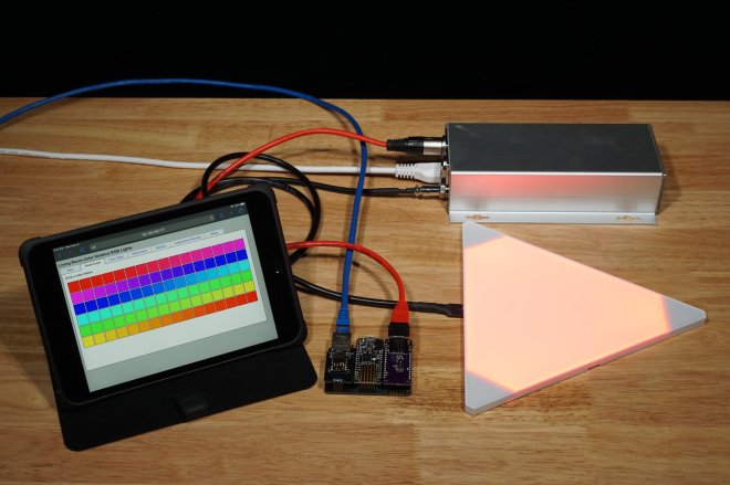
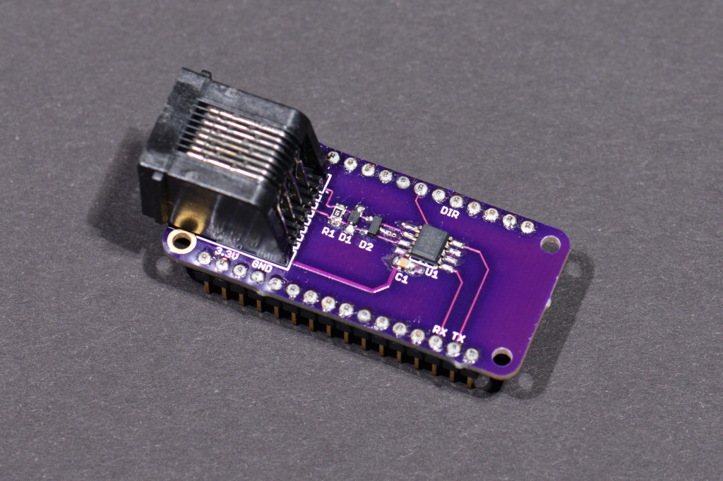
This project uses an Adafruit Feather M0 Basic Proto board to control a group of Color Kinetics or other RGB light fixtures using the DMX-512 protocol. We’ll build a DMX-512 interface FeatherWing then connect it to the Feather M0 using a Particle Ethernet FeatherWing. Once the hardware is built and assembled, we’ll write software with a web-based GUI to generate RGB lighting effects and control the attached RGB lights using the DMX protocol. By modifying the software on the Feather M0, different effects can be generated and added to the web-based GUI.
Required Materials
The materials required for this project are:
- DMX FeatherWing board and parts. We’ll discuss ordering the board, the required parts, and the assembly in the next section.
- Adafruit Feather M0 Basic Proto
- Particle Ethernet FeatherWing
- Particle Ethernet FeatherWing PoE Adapter (optional). Note: The PoE adapter has been discontinued. If you want to make your own version, the Eagle design files are available here but the header sockets on the module need to be moved to align with the headers on the Ethernet FeatherWing board.
The DMX FeatherWing
The photo above shows the assembled DMX FeatherWing. The next few sections are dedicated to describing and building the DMX FeatherWing hardware.
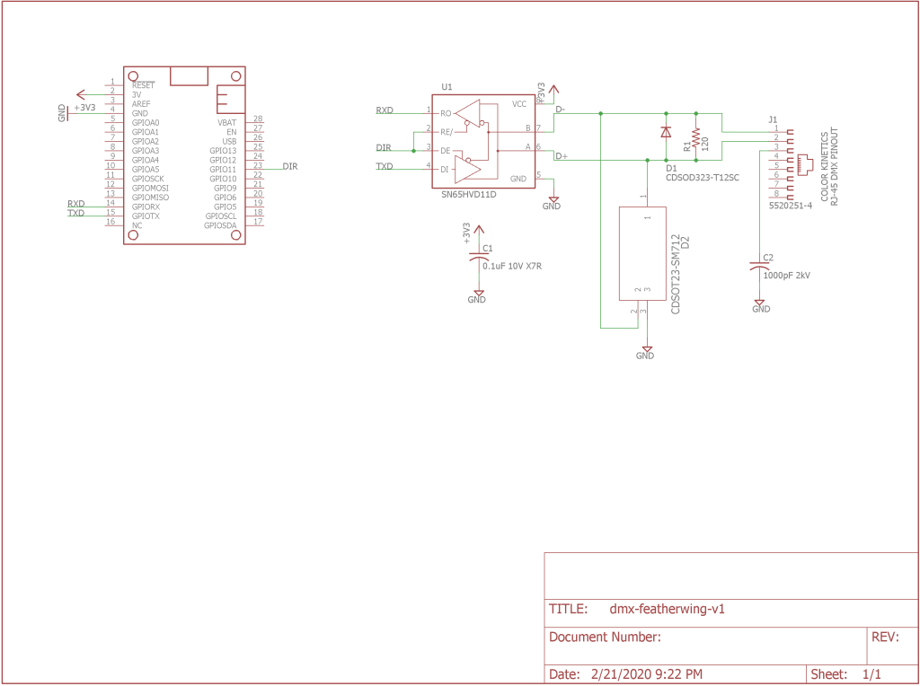
Circuit Design and Schematic
To make sure everything conformed to the FeatherWing form factor, I started with the Eagle design for the Adafruit Power Relay FeatherWing. I deleted everything from the schematic and board except for the FeatherWing symbol and dimension lines. The FeatherWing symbol includes the board outline layer and the holes for the 0.1″ pitch, 0.025″ square post headers that connect the FeatherWing to other boards. I saved this as a new file then started my design.
Winners of the Take Flight with Feather Contest
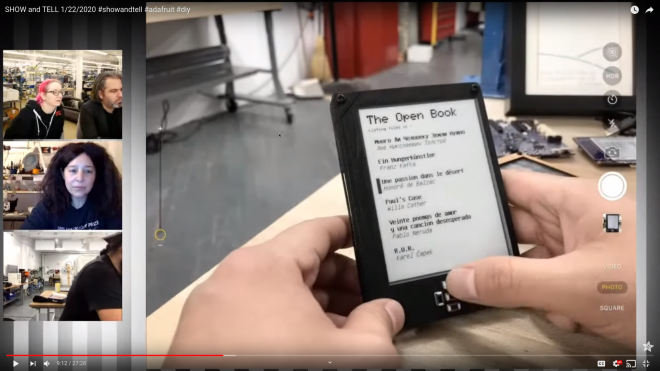
Congratulations to Joey Castillo for winning the Take Flight with Feather contest with the The Open Book by Oddly Specific Objects:
Hackaday: Winners of the Take Flight with Feather Contest
It’s hard to beat the fidelity and durability of printed text on paper. But the e-paper display gets pretty close, and if you couple it will great design and dependable features, you might just prefer an e-reader over a bookshelf full of paperbacks. What if the deal is sweetened by making it Open Hardware? The Open Book Project rises to that challenge and has just been named the winner of the Take Flight with Feather contest.
This e-reader will now find its way into the wild, with a small manufacturing run to be put into stock by Digi-Key who sponsored this contest. Let’s take a closer look at the Open Book, as well as the five other top entries.
You may remember seeing the Open Book back in October when Tom Nardi looked in on early testing for the board. It was prototyped using the Adafruit Feather, which of course was the main requirement of the contest. The controller is now built into the board for standalone functionality with the Feather header providing an opportunity for expansion.
The screen is 4.2″ with a resolution of 300×400. It reads files from a microSD card and uses seven buttons on the front of the board for user input. A dedicated flash chip stores language files with the character sets of your choice. The small LiPo cell can be charged via the USB port, and of course e-paper helps greatly in reducing the power consumption of the reader.
You’ll find a few extras on the back. There’s a headphone jack for listening to audio books, and get this, a built-in microphone and a TensorFlow-trained model allow for voice control! There are STEMMA headers to add your own hardware options, and designs for laser-cut and 3D-printed enclosures.
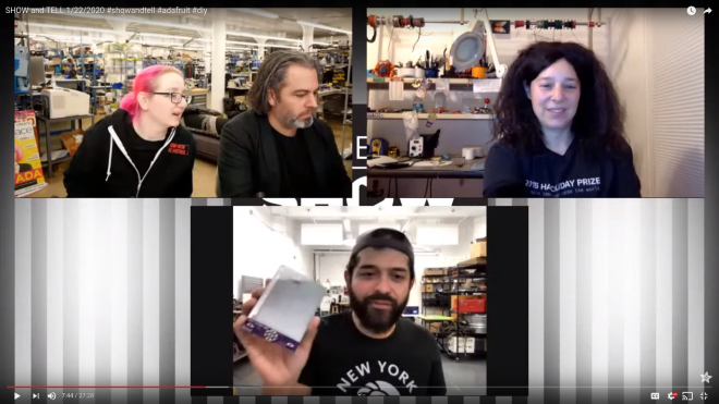
and checkout Joey on Adafruit Show n Tell last night!
The first Adafruit Show ‘n Tell of 2020
Joining Adafruit Show ‘n Tell with Helen Leigh was a fun way to start 2020!
Helen embroidered the CircuitPython-powered Serpente board from Arturo at Chaos Communication Congress (36c3):
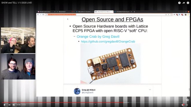
I showed Linux running on a RISC-V core in the ECP5 FPGA on the Hackaday Supercon badge:
I gave a shout-out to Greg Davill who got Linux booting the OrangeCrab while at 36c3:
Greg’s open hardware OrangeCrab board features the ECP5 FPGA in an Adafruit Feather form factor and is capable of running a RISC-V “soft” core using LiteX.
Find out more about Linux on RISC-V using open source FPGA toolchains in the slides from my 36c3 talk
KiCad teardop plugin and flexible PCBs
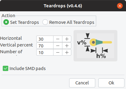
Thanks to Anool posting on Hackaday about KiCad plugins. I decided to try out the Teardrop plugin by NilujePerchut:
KiCad Teardrop Plugin
This action plugin adds and deletes teardrops to a PCB.
This implementation uses zones instead of arcs. This allows to comply with DRC rules by simply rebuild all zones. You can also modify their shape by simply modifying the zone outline (like any other zone). Teardrops created with this script use a specific priority (0x4242) to be recognized as teardrops.
Here is the result of my first experiment to use the Teardrop plugin on a flexible PCB to reduce the mechanical stress of flexing the trace:
The board is available as an OSH Park shared project and the KiCad design files are on GitHub.
The author of the plugin was very responsive to GitHub issues and I was able to get better results on my next flex design which is currently being manufactured:
My flex “business card” will fold over a coin cell battery to light a 0603 LED.
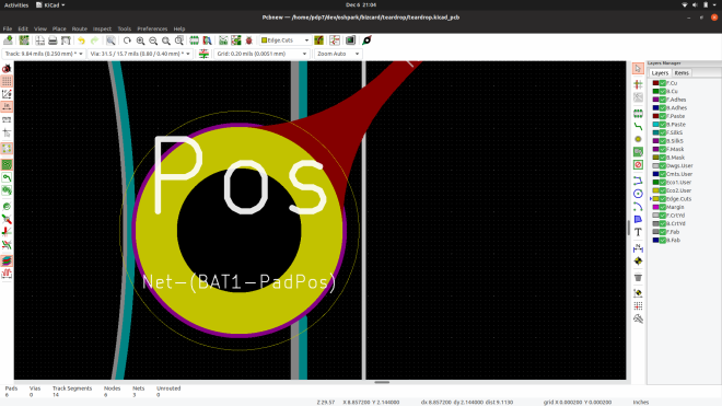
Curious how the plugin works? It creates zones next to the vias and pads. Here are the two teardrop zones that connect traces to a via:
Warning: you need create a schematic and generate a netlist before starting the PCB layout. Otherwise the the zones the plugin creates won’t be filled:
You also need to be careful that there is not copper on the same layer too close to the zone. For example, the text was too close to the teardrop zone on this via, so I moved the text down and the zone now fills correctly:
An open GitHub issue is that the teardrop zone does not align perfectly for SMD pads that are not circles (like rectangles, squares, rounded rectangles). The work around I used was to move the zone after it is filled to align with my SMD pad:
I hope you have fun with this plugin and leave a comment if you use it your own design!
UPDATE: I joined Adafruit Show-n-Tell to talk about flex PCBs and the teardrop plugin at 10 min 51 sec mark
CircuitPython in a small factor with CircuitBrains Deluxe
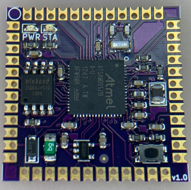
Kevin Neubauer has designed a System-on-Module (SoM) to make it easy to embed Circuit Python in project:
CircuitBrains Deluxe
I love Adafruit’s CircuitPython product line. The ability to just plug your board into USB, make code changes, and see them take effect in real-time is amazing. However, when it comes to finishing up a CircuitPython project, I felt limited in choice for a small form-factor, streamlined board. I always ended up creating my own boards. The overhead in doing this was huge though. You have to make sure your design has proper power, decoupling, and clock. Then you source all of the parts. After that you lay out the PCB and have it fabricated. When the PCB and parts arrive, you have to deal with finicky small-pitch surface mount assembly. Finally, you need to download the sources for the UF2 bootloader and CircuitPython and define your board, compile, and flash. This makes what should be a small project pretty time consuming and tedious!
https://twitter.com/kevinneubauer/status/1204808844293095424
Goals:
- Reduce barriers to entry for custom CircuitPython-based boards & badges
- Package CircuitPython into a small form-factor module that will add minimal dimensions to a parent project
Specs:
- Dimensions: 29 x 29 x 3.5 millimeters / 1.15 x 1.15 x 0.15 inches
- Atmel ATSAMD51J19A Microcontroller (32-bit ARM Cortex M4)
- 120 MHz
- 192 KB SRAM
- 512 KB Flash
- 8 MB SPI Flash
- Onboard 3.3V LDO Regulator
- Power and Status LEDs
- Breakouts for SPI and I2C
- Breakouts for 14 Analog and 19 Digital Inputs/Outputs

