Building an FPGA board for VGA graphics

From Benjamin Blundell:

Field programmable gate arrays, or FPGAs are wonderful little devices. In a nutshell, they are a whole load of logic blocks, wired together with interconnects. These logic blocks can be wired up however you like, to create simple, or complicated circuits. Anything from a simple XOR gate, to a CPU, to an entire system (if you have enough money to buy the biggest ones). Think of them as a big box of lego bricks that you can combine in any way you want to create any kind of digital circuit.
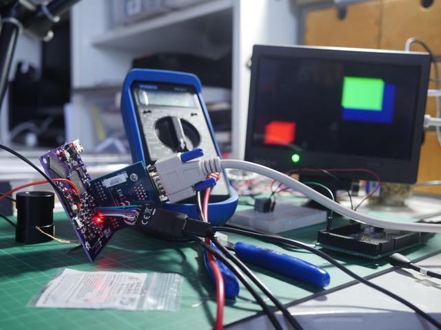
FPGAs have been used in many applications – emulation of older systems being one. The MiSTer is one such example. Jeri Ellsworth’s C-One is another. But really, FPGAs are found everywhere. They are quick, robust and adaptable to most situations.

My friend Will runs the Project-F website where he investigates all things FPGA. I’ve been helping out by building some boards for us, and this is one of the first. I’d like to show you all how I went about building one of our early prototypes, the triumphs and pitfalls and hopefully inspire folks to give it a go themselves.

Read more…

Building an FPGA board for VGA graphics

BGA Soldering and Inspection — Hackaday

If you want to build cool things these days, you’ve probably had to master surface mount electronics. However, for many people, ball grid array (BGA) is still intimidating. Have a look at [VoltLog’s] video about his techniques for soldering BGA and inspecting that you managed to do it right.

He’s got quite a few tips about things like surface finish and flux selection. It looks easy when he does it. Of course, having a good PCB with good registration markings will help too.

You can’t get a soldering iron under the part, of course. A hot plate provides heat from underneath. A gentle push from a hot air gun will push the solder balls over the melting edge. Even taking the part off the hotplate requires a special technique.

Without seeing the result, how can you know if it was successful? Pros can use an X-ray machine, but you probably don’t have one of those sitting in your shop. [VoltLog] uses a DVM and tests the internal protection diodes that the chip almost certainly has on its pins. However, to do that, you need to put the chip on a bare board. If you were repairing an existing board, the technique wouldn’t be useful since other components on the board would throw the measurements off.

Read more on Hackaday…

BGA Soldering and Inspection — Hackaday

Retro CPC Dongle: advise on tented vias

Advice from the Intelligent Toasters blog on how to do tented vias in DesignSpark PCB software:

Retro CPC Dongle – Part 37

Tented Vias – who’d have thought they play such an essential role? If you have no idea what tented vias are, then you’re not alone and I’m here to enlighten you.


Quote

Building an ARM based microcomputer at home

Having my reflow solder oven finished, I couldn’t wait to see how far can I challenge it with complex circuit boards and tiny components. I decided to build a system with components that are tricky to solder, such as BGA and QFN packages. Not interested in designing the whole circuit on my own, I […]

via Building an ARM based microcomputer at home — HELENTRONICA

Building an ARM based microcomputer at home