Raspberry Pi CAN-bus HAT for the Omzlo IoT platform

From Omzlo Electronics:

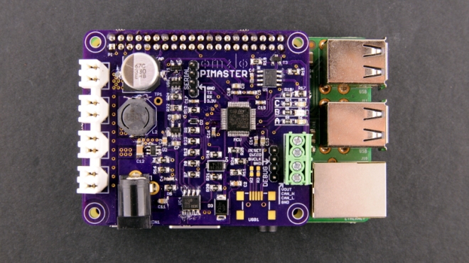
omzlo-pi-master-rpi.jpg

A Raspberry Pi CAN-bus HAT for the Omzlo IoT platform

In a previous blog post, we described “SKWARE” our revised Arduino-compatible IoT modules. These nodes are designed to be connected together in a daisy-chain fashion with a single cable that brings both DC power and CAN-bus networking. The voltage transported in the cables is not 5V (or 3.3V) but rather 12V or 24V to work more comfortably over long distances, potentially reaching 300 meters (1000 feet). You can think of it as a poor-man’s PoE.

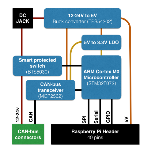
omzlo-pi-master-diagram

This network of connected nodes is designed to be monitored and controlled by a “master node”, which injects the necessary 12V/24V DC, provides node management services and a web interface for network administration. While the IoT nodes are based on an Arduino-style microcontroller, the “master node” requires a bit more power. In this context, the ubiquitous Raspberry Pi with its GPIO header seems like an ideal candidate for that role and we decided to see if we could build a “master node” by augmenting a Raspberry Pi with an appropriate add-on board. These add-on boards are called “HATs” (for “Hardware Attached on Top”) and we called our first prototype the “Pi Master HAT”.

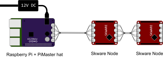
omzlo-pi-master-network

The drawing below illustrates the general structure of our network. A Raspberry Pi equipped with our “Pi Master HAT” controls a network of 2 (or more) daisy-chained nodes, like the SKWARE.

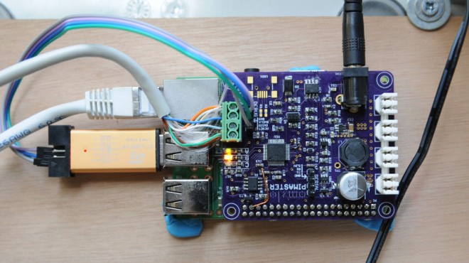
omzlo-pi-master-debug

Raspberry Pi CAN-bus HAT for the Omzlo IoT platform

CANoolder: CAN to 3.3V interface

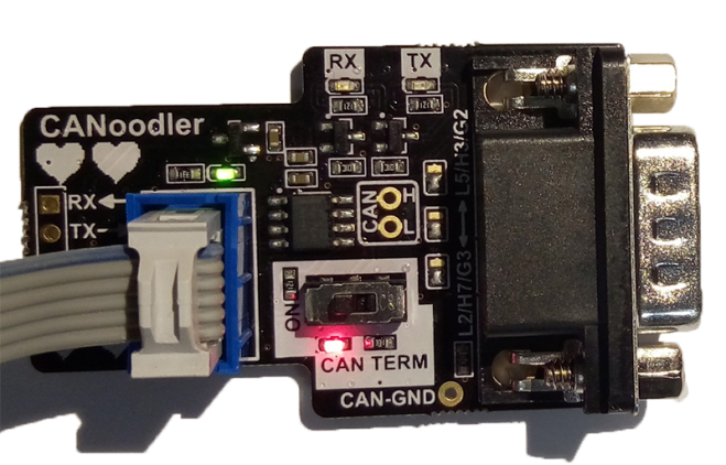
Colin O’Flynn of NewAE designed this simple CAN to 3.3V logic level interface:

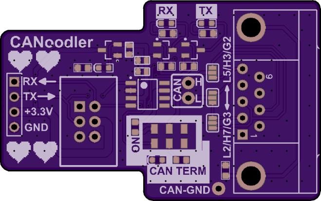
CANoodler_assembled.png

CANoodler

CANoodler is a simple CAN (not CAN-FD) interface, which provides logic-level 3.3V output. It’s designed to be used with microcontrollers that have CAN blocks inside them, and in particular uses a pinout on some ChipWhisperer CW308 (UFO) Target boards.

It’s kinda nice (I think anyway) since it has these features:

  • LEDs for TX/RX (uses MOSFET to drive LEDs so doesn’t slow your I/O pins down).
  • Reverse-polarity protection on 3.3V input.
  • Switch for CAN termination on/off with LED feedback.

The design files are available on GitHub:

newaetech/CANoodler

Screenshot from 2017-08-28 01-38-11

coflynn has shared the board on OSH Park:

CANoodler – CAN to TTL Interface

bf472e82dc546a6961d4fb364dbf77c2.png
Order from OSH Park

CANoolder: CAN to 3.3V interface

EDm: OBDII CAN bus BLE dongle

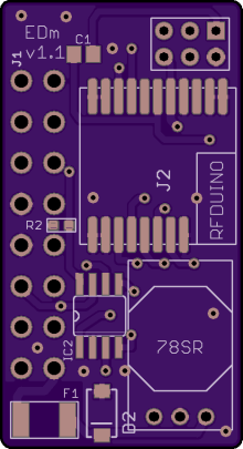
MyLab-odyssey created this board tho monitor the status of your Smart electric drive EV with this RFduino CAN bus dongle and the Blynk app on your mobile phone:

images1MyLab-odyssey/EDm_BLE


Hardware used:

  • RFduino MCU & BLE
  • MCP2515 CAN controller
  • MCP2562 CAN transceiver + ESD diode
  • OKI 78SR DC/DC for efficiency.

MyLab-odyssey has shared the boards OSH Park:

EDm_v1.1.brd

b964b51e3009e2b4bf91240452ca7c56

Order from OSH Park

EDm: OBDII CAN bus BLE dongle