PixelWing takes flight

Our friends at Oak Development Tech designed this WiFi + RGB matrix display which combines the power of ESP32-S2 and SK6812mini:

PixelWing ESP32-S2 RGB Matrix

The PixelWing Matrix is a powerful ESP32-S2 RGB Matrix Display board that allows you to make a simple connected display, data logger, or environmental indicator. The PixelWing features USB-C power, a 5×10 RGB Matrix Display using SK6812mini Addressable LEDs that are compatible with Adafruit NEOPIXEL Libraries!

In addition to this, the PixelWing provides a quick access I2C JST connector that is compatible with Qwiic and Stemma QT connectors allowing you to connect all your favorite Adafruit and Sparkfun sensor breakouts.

All of this is combined with Circuit Python support making it easy to get programming on your project.

PixelWing takes flight

Obsidian Boa: Greg Davill squeezes the ESP32 into a ItsyBitsy

Tom Fleet writes on Hackster about the latest open source board from the prolific Greg Davill:

image_AA1rCHSTD2

Meet Obsidian Boa: This ItsyBitsy — with WiFi — Is What It’s All About!

No, we’re not branching out into nursery rhymes, but it’s too hard to pass up on the chance offered by the latest development from Hackster favorite Greg Davill!

With the dust in his workshop only just settling (if that’s possible there…) from his successful OrangeCrab crowdfunding campaign, he’s gotten straight back to work, turning his sights from the Lattice ECP5, and setting them squarely on the Espressif Systems ESP32, with his latest creation — the ObsidianBoa!

While the above image is a render, the quality of Davill’s work shines through in both the the physical and the virtual world — some of his recent rendering work is hard to tell from reality.

image_hwhyR3mzg6

While there are a number of ESP32 development boards, there are few in such a diminutive form factor. The only one I know of, until now, has been the TinyPICO, from @unexpectedmaker. This is a fantastic board in it’s own right, and has been rightfully successful within the maker community.

Obsidian Boa has a few notable differences however, which might make it more suitable for certain applications.

The first point of note is where we get the title of this article from. Not just a descriptive phrasing, ItsyBitsy is a lesser-heard-of form factor — and just as we all know boards in the Arduino R3 layout, or the hugely popular Feather form factor from Adafruit, ItsyBitsy started out life as yet another Adafruit board format, and was shortly thereafter realized as a baby brother alternative to the well known iCEBreaker FPGA boards.

image_3w3adIdgXw

Obsidian Boa: Greg Davill squeezes the ESP32 into a ItsyBitsy

ESP32-S2 Hack Chat with Adafruit on Hackaday

AdafruitESP32HackChatPosterV1_1-01

Join us on Wednesday, May 6 at noon Pacific for the ESP32-S2 Hack Chat with Limor “Ladyada” Fried and Scott Shawcroft!

When Espressif released the ESP8266 microcontroller back in 2014, nobody could have predicted how successful the chip was to become. While it was aimed squarely at the nascent IoT market and found its way into hundreds of consumer devices like smart light bulbs, hackers latched onto the chip and the development boards it begat with gusto, thanks to its powerful microcontroller, WiFi, and lots of GPIO.

The ESP8266 was not without its problems, though, and security was always one of them. The ESP32, released in 2016, addressed some of these concerns. The new chip added another CPU core, a co-processor, Bluetooth support, more GPIO, Ethernet, CAN, more and better ADCs, a pair of DACs, and a host of other features that made it the darling of the hacker world.

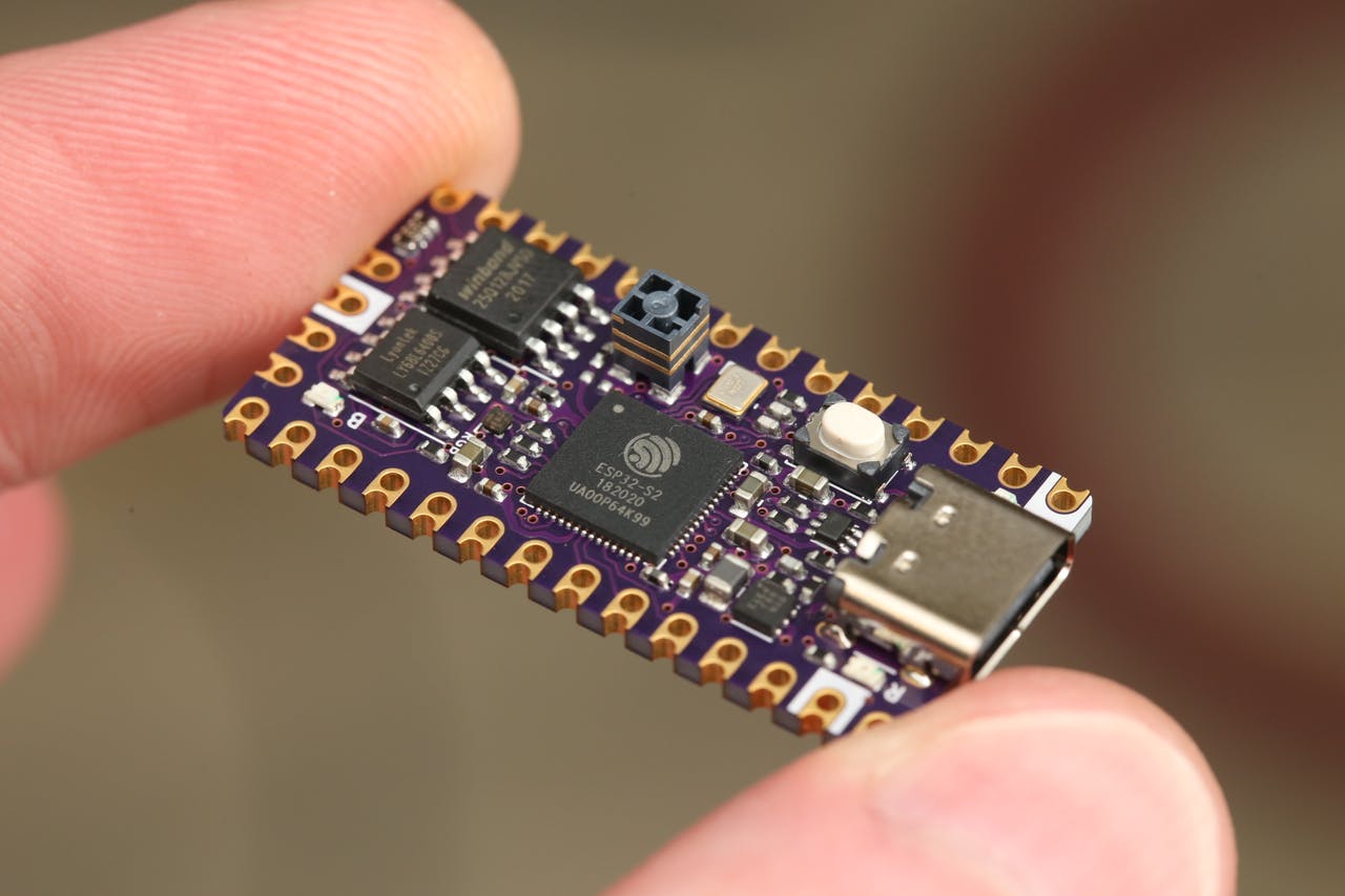
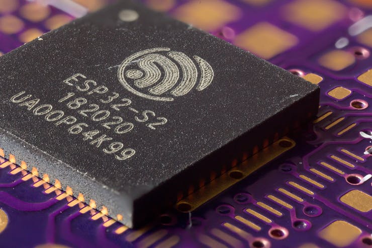
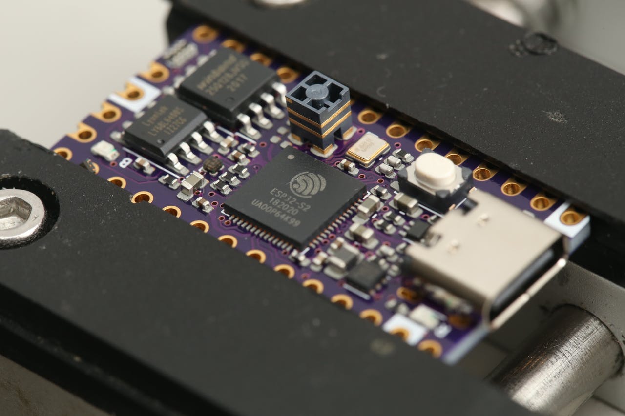
Now, after being announced in September of 2019, the ESP32-S2 is finally making it into hobbyist’s hands. On the face of it, the S2 seems less capable, with a single core and neither Bluetooth nor Ethernet. But with a much faster CPU, scads more GPIO, more ADCs, a RISC-V co-processor, native USB, and the promise of very low current draw, it could be that the ESP32-S2 proves to be even more popular with hobbyists as it becomes established.

To talk us through the new chip’s potential, Limor “Ladyada” Fried and Scott Shawcroft, both of Adafruit Industries, will join us on the Hack Chat. Come along and learn everything you need to know about the ESP32-S2, and how to put it to work for you.

join-hack-chatOur Hack Chats are live community events in the Hackaday.io Hack Chat group messaging. This week we’ll be sitting down on Wednesday, May 6 at 12:00 PM Pacific time. If time zones have got you down, we have a handy time zone converter.

Click that speech bubble to the right, and you’ll be taken directly to the Hack Chat group on Hackaday.io. You don’t have to wait until Wednesday; join whenever you want and you can see what the community is talking about.

via ESP32-S2 Hack Chat with Adafruit — Hackaday

Quote

Low Power ESP32 Handheld

Max.K on Hackaday.io has created a pocket sized ESP32 display board with 300µW Always On Display:

7327171577179362033.jpeg

Low Power ESP32 Handheld

This handheld board is powered by an ESP32 and features a transflective Sharp memory LCD.  Similar to my previous Chronio smartwatch the focus of this project is on low power consumption.  Using the ESP32’s ULP core, the board can go into deep sleep with an active display.   The software includes a menu interface with a simple RSS reader.

Some of the key features are:
– 400x240px 2.7″ SHARP memory display
– 350 mAh LiPo battery with USB charging
– Always On Display with 300 µW power consumption
– 4-way joystick and buttons
– Date and time using built in RTC with NTP sync
– RSS Feed / Website parser

Layout files and Code on GitHub: https://github.com/CoretechR/ESP32-Handheld


Low Power ESP32 Handheld

#badgelife add-on adapter for Adafruit LED matrix

Dqu6j8vX0AAwGG4

Adapter board to attach Adafruit 8×8 LED Matrix board as #badgelife add-on (using the DC26 SAO 2×2 pin header)

KiCad design files:

OSH Park shared project:

#badgelife add-on adapter for Adafruit 8×8 LED matrix

d68231e20e8a38d08579fd6c33f80553 (1)

Order from OSH Park

MicroPython support:


Resources:

#badgelife add-on adapter for Adafruit LED matrix

Bring your Open Hardware Summit badge to Hackaday Supercon

Bring your Open Hardware Summit badge to Hackaday Supercon in Pasadena this weekend!

Drew Fustini will have the badge programming jig with updated firmware featuring like the MicroPython WebREPL, accelerometer demo, and Magic 8-Ball app by Steve Pomeroy

Screenshot from 2018-10-30 11-48-13.png

Drew Fustini will also have USB-to-serial adapter boards for badge to share!

dpuljnbw0aab7st1


Bring your Open Hardware Summit badge to Hackaday Supercon

MicroPython WebREPL on the Open Hardware Summit badge

The 2018 Open Hardware Summit badge runs MicroPython firmware which allows for an interactive programming experience known as the REPL:

Getting a MicroPython REPL prompt

REPL stands for Read Evaluate Print Loop, and is the name given to the interactive MicroPython prompt that you can access on the ESP8266. Using the REPL is by far the easiest way to test out your code and run commands.

There is an USB-to-serial adapter board which be used to access the REPL on the badge via the serial port.  However, a simpler option is to use the WebREPL:

WebREPL – a prompt over WiFi

WebREPL allows you to use the Python prompt over WiFi, connecting through a browser. The latest versions of Firefox and Chrome are supported.

For your convenience, WebREPL client is hosted at http://micropython.org/webrepl . Alternatively, you can install it locally from the the GitHub repository https://github.com/micropython/webrepl

Before connecting to WebREPL, you should set a password and enable it via a normal serial connection. Initial versions of MicroPython for ESP8266 came with WebREPL automatically enabled on the boot and with the ability to set a password via WiFi on the first connection, but as WebREPL was becoming more widely known and popular, the initial setup has switched to a wired connection for improved security:

import webrepl_setup

Follow the on-screen instructions and prompts. To make any changes active, you will need to reboot your device.

The MicroPython firmware for the badge has been updated to add WebREPL in the list of available apps.

You can order this USB to serial adapter board for the badge and then follow the instructions to build and flash the new firmware.  The WebREPL option will turn on WiFi and put the badge into AP mode.  Connect to it from your device, such as a laptop, and then connect to the badge using the WebREPL browser-based client.

Resources:

MicroPython WebREPL on the Open Hardware Summit badge

OHS18 badge: accelerometer demo, adapter board, Tindie listing

Updates for the 2018 Open Hardware Summit badge project:

MicroPython demo app for the Accelerometer

Want to use the KX122-1037 Accelerometer (datasheet) on the 2018 Open Hardware Summit badge?

USB-to-Serial adapter board

This adapter board to connects a USB-to-serial cable to the 2018 Open Hardware Summit badge.

Extra badges being sold on Tindie

The extra badges from the Summit are being sold here on Tindie as a fundraiser for the Ada Lovelace Fellowship which provides travel assistance to the Open Hardware Summit. All sales revenue will be 100% donated to the Open Source Hardware Association (OSHWA) for this purpose.

OHS18 badge: accelerometer demo, adapter board, Tindie listing

USB-to-serial adapter board for Open Hardware Summit badge

This adapter board to connects a USB-to-serial cable to the 2018 Open Hardware Summit badge.

DpulizcW0AABn7E

The badge features an ESP32 microcontroller running MicroPython firmware.  The firmware provides a Python interpreter prompt (REPL) on the serial port which allows interactive programming of the badge!

DpuljnbW0AAb7st

A previous blog post describes how to build and flash new MicroPython firmware to the badge:


The KiCad design files are shared on GitHub:

oshwabadge2018/adapter-board

Screenshot from 2018-10-20 02-25-11.pngThe board has been shared on OSH Park:

OSH Park: adapter board for USB-to-serial cable

Screenshot from 2018-10-18 00-02-21

Order from OSH Park

Bill of Materials (BoM)

  • Switch for programming mode
    • E-Switch EG1218
    • Slide Switch SPDT
    • Digi-Key: EG1903-ND
  • Pushbutton for reset
    • Omron B3F-1000
    • Tactile Switch SPST-NO
    • Digi-Key: SW400-ND
  • Header for FTDI usb-to-serial cable
    • TE AMP 9-146282-0-06
    • 1×6 Pin Header 0.1″ pitch
    • Digi-Key: A34253-06-ND
  • Header to connect J1 socket on badge
    • Harwin M20-9720345
    • 2×3 Pin Header 0.1″ pitch
    • Digi-Key: 952-1921-ND
  • J1 header socket on the badge
    • Harwin 952-1781-ND
    • 2×3 Header Socket 0.1″ pitch
    • Digi-Key: M20-7830346

Digi-Key shopping cart

Screenshot from 2018-10-20 02-28-43

Resources:

USB-to-serial adapter board for Open Hardware Summit badge

Open Hardware Summit badge: accelerometer demo

IMG_20181016_084030

Want to use the KX122-1037 Accelerometer (datasheet) on the 2018 Open Hardware Summit badge?

Step 1:

Make sure that R12 and R13 are populated.

IMG_20181004_202602 (1)

R12 and R13 are 2.2K Ohm resistors for the I2C bus.  This is needed for the accelerometer to work.  We mistakenly had DNP (do not place) on the BoM (Bill of Materials) for R12 and R13.

IMG_20181004_202414 (1)

Awesome people at Artisan’s Asylum makerspace helped to solder these resistors on the badges right before Open Hardware Summit! 💜✨

It is possible that some badges were not reworked.  Please email [email protected] if they are missing from your badge.

This photo shows what is will look like when R12 and R13 are missing:

IMG_20181004_213549

Step 2:

Download the Python file named accelerometer.py from the ohs18apps repository on GitHub:Screenshot from 2018-10-17 23-35-18.png

Start the FTP server and connect to the SSID listed on the badge:

Open your FTP client application and connect to 192.168.4.1:
Screenshot from 2018-10-03 23-58-59

After the transfer completes, power cycle the badge by removing the batteries and reinserting.

Press the left application button (with the paintbrush and pencil icons) to enter the menu.  accelerometer.py should then be listed under Available Apps menu.  Press the down cursor until accelerometer.py is selected and then press the application button again.

IMG_20181016_083924

Step 3:

The KX122-1037 Accelerometer datasheet describes the 3 different axis:

Screenshot from 2018-10-17 21-25-45

Here are examples of the X, Y and Z axis of the accelerometer for reference:

Resources:

Open Hardware Summit badge: accelerometer demo