Banana Split macropad

Cameron Coward writes on Hackster about a creative macropad project:

Banana Split Is the Potassium-Rich Macropad You’ve Been Craving

We see a lot of macropads around here and so we only feature those that stand out — usually those that incorporate interesting features or that contain unusual hardware. Aesthetics alone aren’t enough to warrant a full write-up unless the device is particularly polished. But the Banana Split, a banana-themed wireless split macropad, is just too delicious to pass up.

Banana Split macropad

Open-Hardware STM32 Firefly BLE Dev Board

Gareth Halfacree writes on Hackster:

PeskyProducts, Tlera Corp Launch Open-Hardware STM32 Firefly Bluetooth Low Energy Dev Board

Available to order as a PCB from OSH Park or a completed unit from Tindie, this compact Arduino-compatible aims to make BLE a cinch.

PeskyProducts and Tlera Corp have designed an open-hardware development board for Bluetooth Low Energy (BLE) projects, built around STMicro’s STM32 microcontroller and boasting full Arduino IDE support: the Firefly BLE.

“This is a small, open source hardware implementation designed to make using and customizing the STM32WB55 easy for everyone,” Tlera Corp explains of the Firefly BLE’s design. “It supports iBeacon, NUS, BlueST protocols as well as standard and custom BLE services and characteristics.

“For several years we have been making use of ST’s STM32L4 family of ultra-low-power MCUs in a variety of applications including development boards, asset trackers, and environmental monitors. Often we include a BMD-350 (nRF52) module for BLE connectivity with smart devices like Android and IOS phones, etc. With the new dual core STM32WB55 MCU, we can now make devices similar in cost, size, and functionality to those we have been but also have the added benefit of embedded BLE connectivity.”

Open-Hardware STM32 Firefly BLE Dev Board

The nRF9160 Feather Is Now Served

Jared Wolff has design a Feather form factor board with the nRF9160:

_vuhruzmxps_blob_LWby6zDhG2

The nRF9160 Feather Is Now Served

Low-power shutdown, built-in 4FF SIM card slot, flexible power supply, and more.

I was a complete failure. My prototype wasn’t working. I spent at least an hour trying to rework a frustratingly large LTE module on an impossibly small circuit board.

It wasn’t going to work.

So I went back to the drawing board. I poured my years of hardware experience into a tiny form factor.

The end product?

Something smart. Something with LTE, NB-IoT, and GPS. Something anyone could get started with right away.

And thus, the nRF9160 Feather was born.

I need your help! 🙏

To make this campaign a reality, I need your help to meet our minimum order quantity of nRF9160 Feathers. Without that, we’re dead in the water! Head on over to the campaign page to reserve yours.

For those of you who’ve already committed, I thank you from the bottom of my heart. I can’t wait to get the nRF9160 Feather into your hands!

P.S. Huge thanks to Hackster and GroupGets for making this happen. You guys and girls are great. ❤

untitled_2_FCqZNSHpTW

The nRF9160 Feather Is Now Served

Build Your Own RF Lab: Scalar Network Analyzer

Whitney Knitter writes on Hackster about a simple scalar network analyzer that can be controlled by a Raspberry Pi for measuring the frequency response of filters and networks:

screen_shot_2020-06-21_at_12_39_16_am_QwvfFybZEx

Build Your Own RF Lab: Scalar Network Analyzer

With the popularity of wireless applications having become such a staple in the hobbyist community, the need for RF testing capabilities in the hobbyist realm has also increased. Anyone familiar with traditional RF test equipment knows that it is expensive. But challenges like this are what bring out the engineering creativity in this community. Steven Merrifield designed and laid out his own simple scalar network analyzer (SNA) using just a few IC chips. SNAs are handy for testing the frequency response of filters or networks.

A scalar network analyzer is used to test the amplitude of a device’s frequency response by outputting a sine wave sweeping over a certain frequency range (bandwidth) then measuring the amplitude of each incremental output frequency.

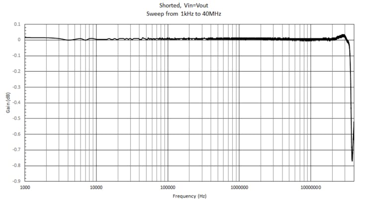
Thus if you directly connect the sine wave output of an SNA to its measurement input, then it will read a flat line of the same amplitude for each incremental output frequency of the sweep:

When a device is connected to the SNA, the amplitude of the sine wave at each frequency after going through the device will reflect the device’s frequency response over that bandwidth.

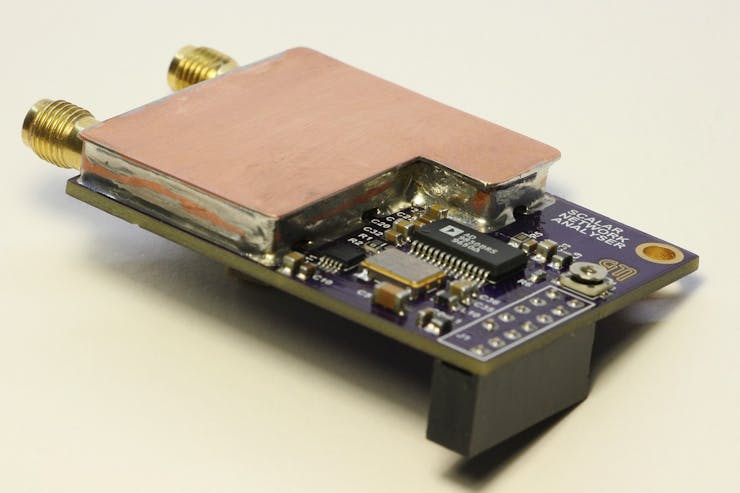
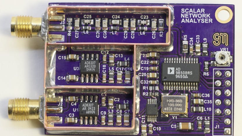
Merrifield’s design accomplishes an SNA’s functionality via implementation of a DDS Synthesizer chip, an ADC, and a logarithmic amplifier chip. The AD9850 DDS is responsible for outputting the sweeping sine wave while the AD8307 logarithmic amplifier conditions the signal input into the SNA for the log of the signal’s envelope before passing it on to the ADC for digitizing. A second AD8307 also conditions the output of the DDS and outputs it to a second channel of the ADC so that it can be used in software for compensation of any variations on the DDS’s output due to the effects of various loads of devices being tested.
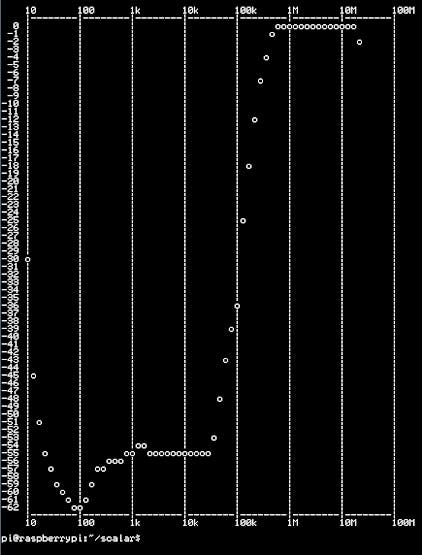
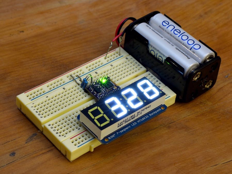
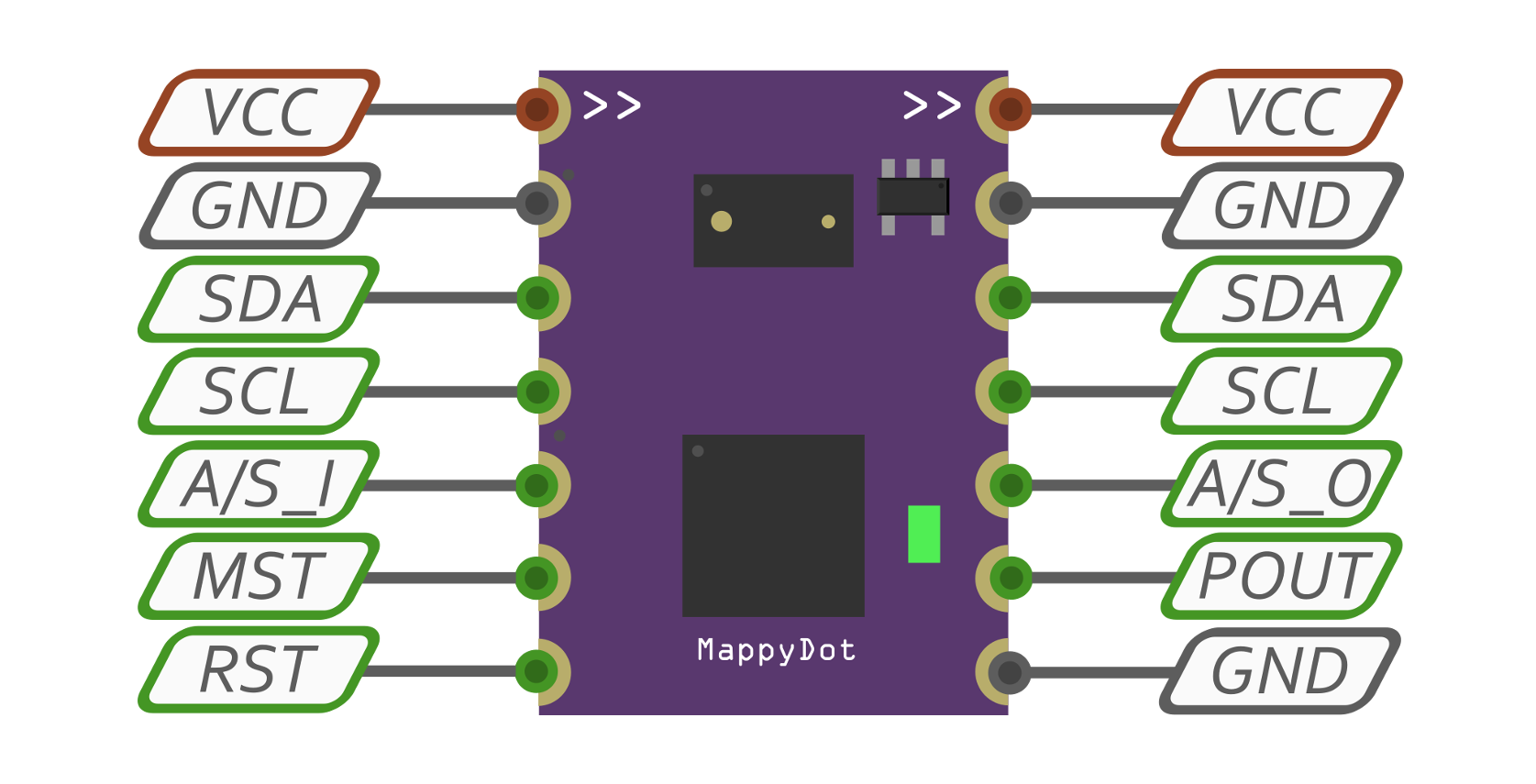
The ADC outputs its digital measurements via an I2C interface to a GPIO header that matches the Raspberry Pi’s GPIO header pinout, but any desired MCU or FPGA could be used. The source code Merrifield wrote is in C, making it easy for porting across different platforms.
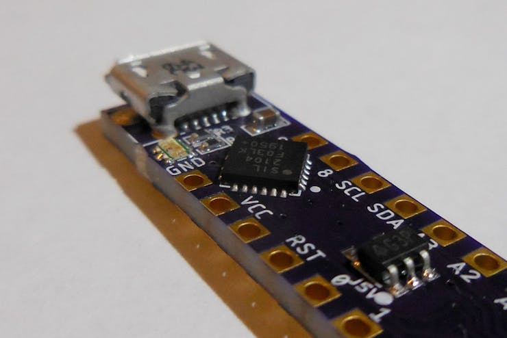
Check out Merrifield’s project logs here. He linked his PCB layout on OSH Park if you’re interested in ordering it and putting one of these together for your own lab!

Build Your Own RF Lab: Scalar Network Analyzer

DipDuino: Arduino-compatible slim as a DIP

AtomSoft has designed this Arduino-compatible board that’s as slim as a DIP chip:

dipbread_SOceNJDsDY

dipDuino Is an Arduino-Compatible Board That’s as Slim as a DIP Chip

Take up fewer rows on your breadboard with this ATmega328P-based board.

One reason the Arduino Nano became a popular form factor is that it fits onto a breadboard. The compact size is nice but makes the board a bit larger in the width dimension. To solve that issue, AtomSoftTech designed the dipDuino as an Arduino-compatible as narrow as a DIP package.

dipDuino has the same ATmega328P found in the other 8-bit Arduino boards like the Uno and Nano, however measures just 0.37 x 1.82 in (9.3 x 46.26 mm) in size. Its DIP package compatibility comes from the pin row to pin row pitch at 0.3 in (7.62mm).

The DIP-compatible form factor has all of the same pins found on those other boards: 13 digital, five analog, VCC, RESET, and GND. The silkscreen labels A4 and A5 as SDA and SCL since they have a shared function (same as the Uno and Nano).

The ATmega328P SMD packages have two extra analog inputs available that the DIP-style package does not. (This difference is why boards like the Pro Mini and Nano have A6 and A7.) Even though dipDuino has an SMD AVR chip, it does not break out the extra analog pins.

DipDuino: Arduino-compatible slim as a DIP

MappyDot Distance Measurement Badge

SensorDots created this standalone wearable badge that will show people how far away they are so they don’t accidentally run into you:
dsc_5468_s_nFtrvT5PAS

MappyDot Distance Measurement Badge

This project will show you how to create a standalone application with the MappyDot Plus working as an I2C master with an I2C 7 segment display. This example can also be adapted for use with a wide range of different client I2C devices for standalone applications.

tindie_layout_U22F4c6FMZlanyard_bb_lsAEQRf88J

Once you have assembled the 7 segment display, you can now hook everything up as per the schematics below. Provided your battery supply outputs a voltage between 2.8 and 5 volts, you don’t need to use a voltage regulator to supply this project. Using 4xAA 1.2v rechargable NiMH batteries is perfect for this setup. If using 1.5V alkaline batteries, you should consider using a voltage regulator (or a diode with a large voltage drop) or opt for only 3xAA alkaline batteries.

MappyDot Distance Measurement Badge

BadgeLove meetup in SF on October 18

Screenshot from 2019-10-12 11-08-37.png

Hackster.io is hosting a BadgeLove meetup in San Francisco on Friday, October 18th:

Have you ever created a badge? Are you currently working on a badge? You are invited as a guest of honor to Hackster’s BadgeLove! Meetup. We want to take an evening to appreciate the hardware heroes who do the often thankless and frequently futile task of creating PCB artwork, shitty add-ons, and PCB badges. 

We are excited to toast the winners of last winter’s BadgeLove! contest on Hackster. Come in person, record a video or join via YouTube Live, and show us what you’ve built.

Screenshot from 2019-10-12 12-49-53


BadgeLove meetup in SF on October 18

Designing a PCB Ornament

Liz from Blitz City DIY wrote about the process of designing a PCB ornament:

edited_p1070247_euwtkNp04o

Designing a PCB Ornament

As the holidays approached this year, I felt a need to create a DIY gift for my family and friends. I struggled at first to find a medium. Should I 3D print something? Should I knit? But then it hit me: everyone loves blinky LEDs and I want to keep getting better at PCB design. I’ll do a PCB ornament!

orbornamentlayout_g9hVPwjRbg

If you don’t have a traditional electronics background PCB design can seem scary, overwhelming and something that’s meant for more experienced people that have “real skills”. If you start simple and slowly add-in new methods and design features to your boards you’ll soon realize it isn’t so scary and that much like everything else in life it just takes practice and patience to learn. And once you have your first project on a custom PCB instead of a piece of perf board you’ll be hooked.

Designing a PCB Ornament

BadgeLove contest on Hackster.io

We are excited to announce this new contest with Hackster.io and Autodesk:

47400396_1866448633452786_2998750869056389120_o

BadgeLove!

BadgeLove by Hackster: The Blinkiest Badge Challenge on Earth! 

Win up to $5,000+ in prizes!

#BadgeLife is the new electronic graffiti. This form of art is in a league of its own, first popularized by DEFCON hackers, now boasts serious technical sophistication, a wicked artistic flair, peppered with political, cryptography, social, cultural and comical narratives, flashing LEDs and screens with add-ons galore.

You are invited to join our first, and certainly not last, BadgeLove challenge, sponsored by OSH ParkAutodesk EAGLE & Fusion 360, and Hackster.

Share your unique design with 700,000+ Hacksters and we will reward badge fanatics for their beautiful, weird, cool contributions.

BadgeLove contest on Hackster.io

New Charmware PCBs by Alex Glow

Screenshot from 2018-08-29 13-45-30.png
Alex Glow from Hackster posted an update on the Charmware modular tech jewelry system:

New Charmware PCBs from OSH Park! (Pt. 1)

Sweet, a package from OSH Park! Time for an unboxing! Plus, see how to upload and order your own boards.

New Charmware PCBs from OSH Park! (Pt. 2)

Visit Hackster.io for more information on the project:

Charmware // Modular Tech Jewelry System

These mini PCB beads (PCBeads?) help you build wearable electronic circuits!

copy_of_workshop_O5TD9874Qs
New Charmware PCBs by Alex Glow