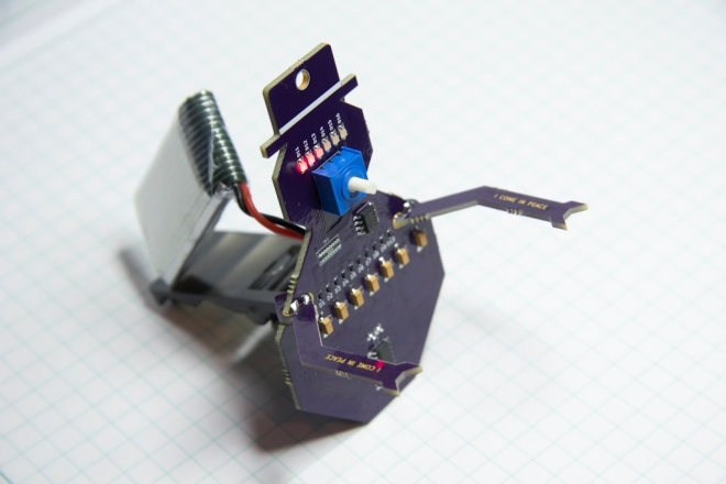
A holiday project by Dan Hienzsch (@rheingoldheavy) to build a little Snowbot with an adjustable speed larson scanner for an eye:

Snowbot V1.0
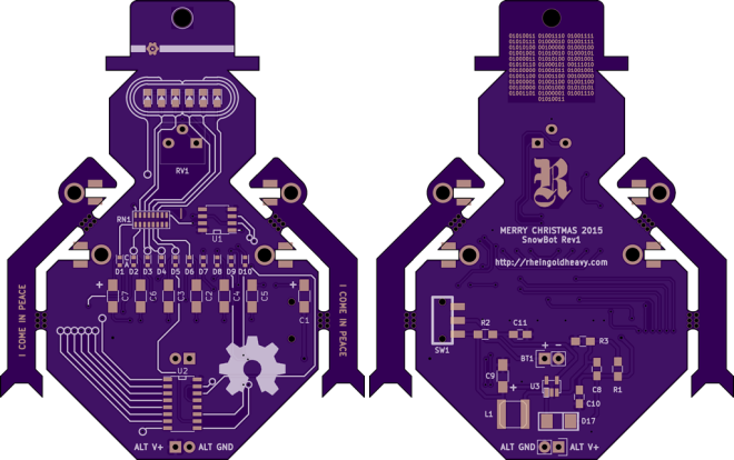
The Snowbot has three major subsystems: Power and Timer and Display.
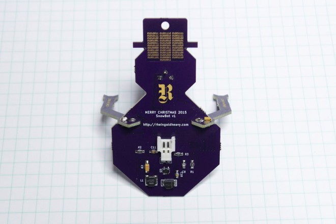
Power Subsystem
The power subsystem uses a 3.7V LiPO battery boosted to 5V with an SC4503 boost converter to power the fully analog circuit. It requires a set of passive components in order to generate the higher voltage.
Timer Subsystem
The timer subsystem is comprised of a 555 IC that generates a clock signal. The speed of the clock is adjusted by twisting the potentiometer (the nose of the snowbot). The clock signal ticks through the outputs of a CD4017 decade counter, lighting each LED in sequence, then moving back through them again.
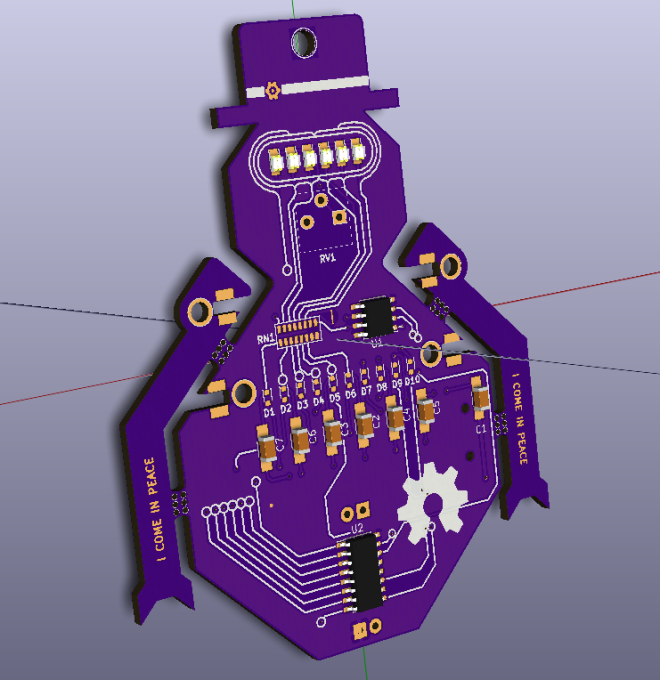
Display Subsystem
The display subsystem involves taking the output of the CD4017, and directing it to six red LEDs in the form of a larson scanner. In addition to lighting the LED, the current also charges a 22uF capacitor through a diode. When the output moves to the next LED, the cap discharges through a 2.2K resistor (part of a resistor network), fading the LED out gracefully.