Bryan Cockfield of Hackaday writes:
Brake Light Blinker Does It with Three Fives
Sometimes you use a Raspberry Pi when you really could have gotten by with an Arudino. Sometimes you use an Arduino when maybe an ATtiny45 would have been better. And sometimes, like [Bill]’s motorcycle tail light project, you use exactly the right tool for the job: a 555 timer.
 More details on William F. Dudley’s project page:
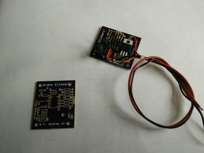
Brake Lamp Flasher for Motorcycle
The 555 is a clever chip; not only will it supply the oscillator for the flashing effect, it has a reset pin that can be used to force the output to a known state (low) when (other circuitry tells it that) it’s time to stop flashing. Thus the brake light will be steady “on” after a few flashes every time the brake is applied.
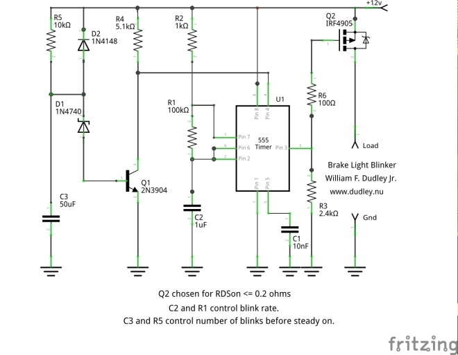
The 555 is happy to run directly off the nominal 12 volt vehicle electrical system, so no voltage regulator is needed. The 555 is almost immune to electrical system noise, so no worries about your Arduino code going off into the weeds if there’s a spike from the electrical system.