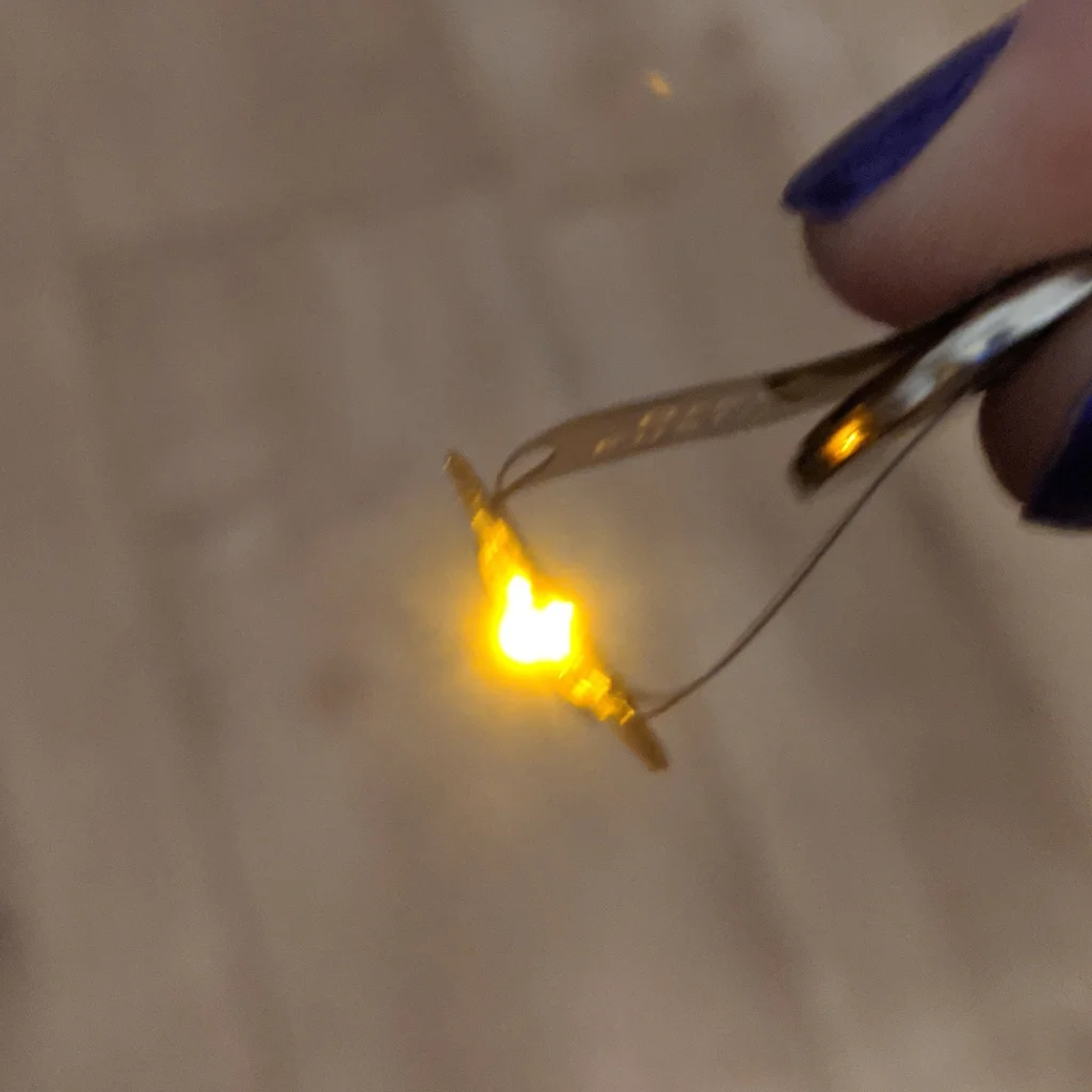
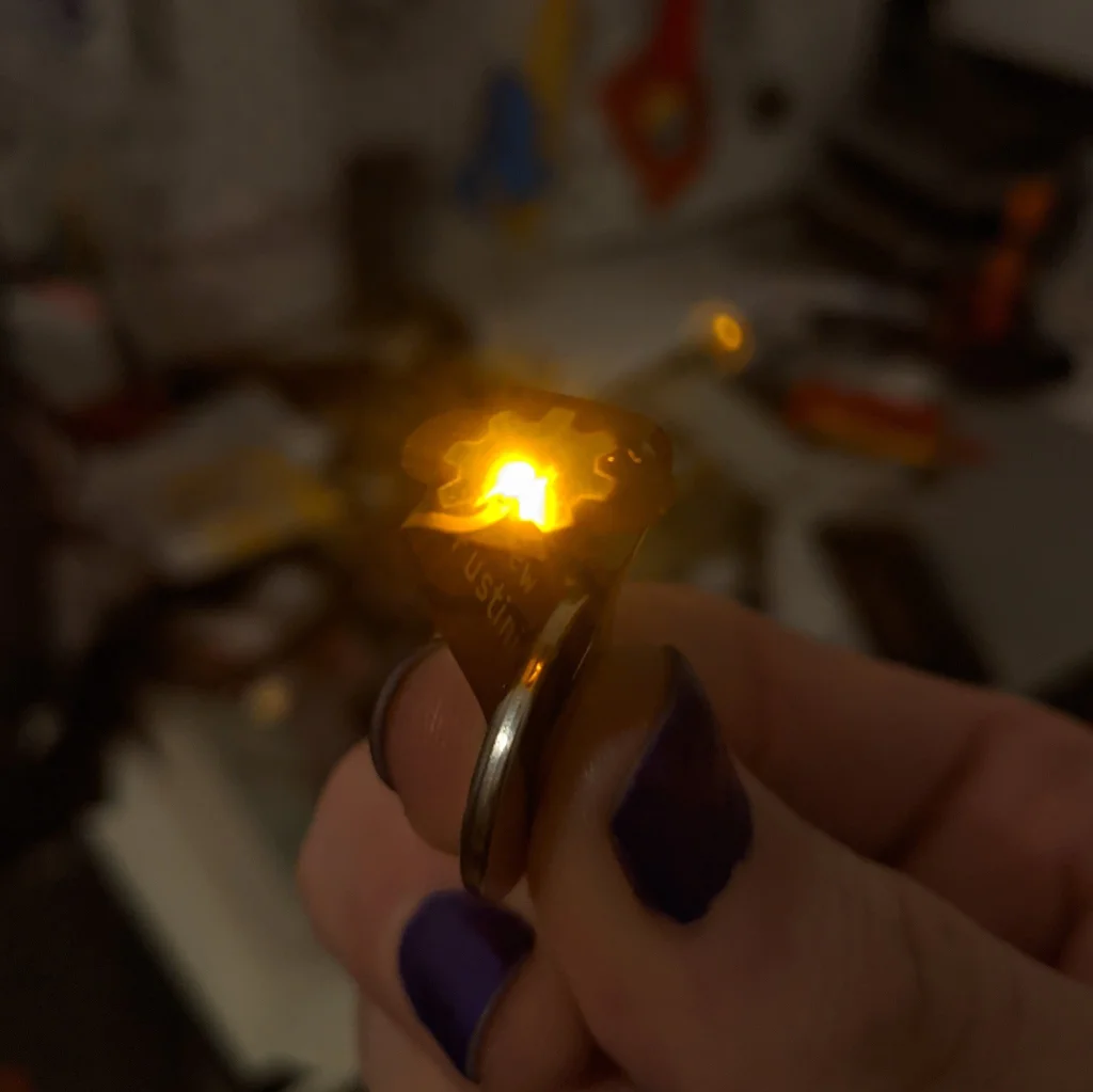
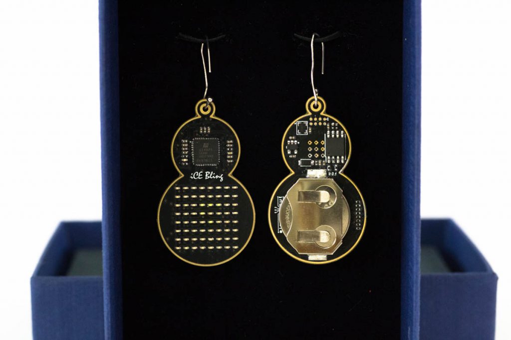
Flexible battery tester

This flexible PCB is designed to a test battery like a CR2032 coincell. The board has cutouts to allow it to fold over the positive and negative terminals and, if the battery has a enough voltage, turn on a LED:

Flexible battery tester

When Toasters Fly…

We love this nod to the After Dark screensaver, back when displays came with degauss buttons. Naturally, Electric Crowbar used our “After Dark” service (clear solder mask on black substrate).

The board is available for order as a shared project:

When Toasters Fly…

Hackaday Remoticon: learn to solder surface mount in style!

The annual Hackaday Supercon is taking place as Remoticon this year on November 6th to 8th. The talented Thomas Flummer has design a PCB badge based on the SMD challenge that can be further customized in KiCad.

There is still time before November 6th to order the board from the shared project page in “After Dark”:

NOTE: make sure to check “After Dark” in the cart

Hackaday Remoticon: learn to solder surface mount in style!

Unofficial Remoticon 2020 badge by Thomas Flummer in “After Dark”

The annual Hackaday Supercon is taking place as Remoticon this year and the talented Thomas Flummer has design a PCB badge based on the SMD challenge that can be further customized in KiCad!

The board can be ordered from the shared project page in “After Dark”:

NOTE: make sure to check “After Dark” in the cart

Unofficial Remoticon 2020 badge by Thomas Flummer in “After Dark”

CR2032 Battery PCB adapter for Yamaha DX7 synth

s-l1600-1

Here is a quick “freebie” of sorts. I’ve had this PCB for a while and used them now and then to fix dead 3v coin cell batteries on Yamaha DX7’s and other synth’s and drum machines. You can order the blank PCBs yourself or download the BRD file and get them made however you want.

OSH Park Shared project MTG CR2032 PCB Saver, Rev A

This item is a battery holder/coin cell adapter PCB that lets you mount a standard CR2032 battery holder over top of a PCB layout that uses a soldered-in battery. It basically converts the pin layout from one of many odd 2- pin and 3-pin board styles into the common battery holder style. In the future, battery replacement will be a snap! Save your gear from leakage, damaged traces and lost sounds! Was designed for Yamaha DX7 synth. The Instructions are here.

s-l1600-2

CR2032 Battery PCB adapter for Yamaha DX7 synth

iCE Bling: Beautiful LED Earrings with Lattice iCE40 FPGA

has created wondeful LED Earrings with the Lattice iCE40UP5k FPGA and shared the project on our website:
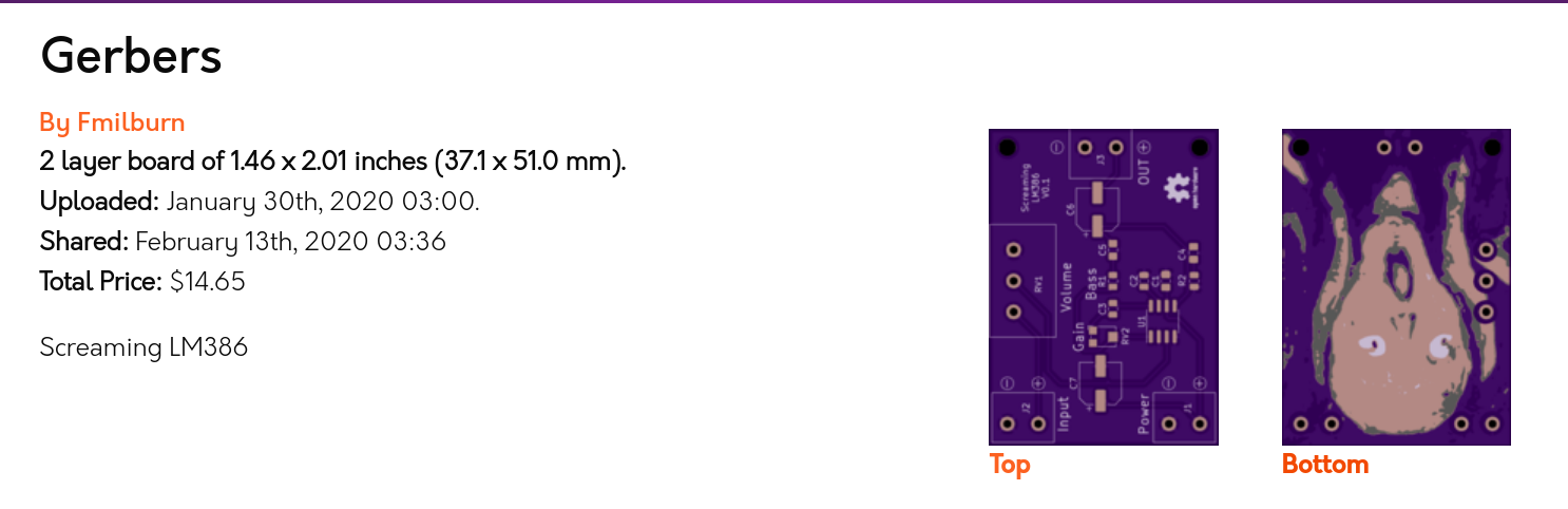
iCEBling

Screenshot from 2020-07-19 14-10-16

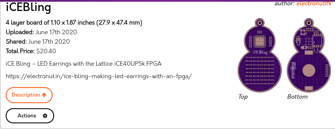
Find out more about the project in this blog post:

ice-bling-sm-1-1024x683

iCE Bling FPGA – Beautiful LED Earrings with Lattice iCE40

It’s the same story every year. At the horizon is a loved one’s birthday, or an anniversary, and I want to make them something special. Buying something won’t do. Oh no, I have to design and build it myself. I would then start with a simple idea, and then complicate it progressively to the point where it would take several anniversaries to finish the project.

This time, I wanted to build a pair of earrings for my wife’s birthday. Since I am learning about FPGAs these days, I wanted to incorporate one into the design. Having gotten older and wiser, I decided to enlist help early on. I would focus on the overall design and the programming part, and leave the PCB design and assembly to my trusted friend and engineer Siva.


iCE Bling: Beautiful LED Earrings with Lattice iCE40 FPGA

Raybeacon 1.4 is out

The rayBeacon by Mike M. Volokhov is a Nordic nRF52 on-the-go development kit:

raybeacon-afterdark

Shared Project: Raybeacon 1.4

The Raybeacon is full-featured nRF52 based wearable, ultra-low power, multiprotocol development board designed for variety of embedded applications. Due to modular design, the device can be used to build your own production-ready appliance with minimal hardware modifications.

Key features include:

  • Coin sized – the board is only 25 mm in diameter
  • Works from a single CR2032 / CR2025 3V button cell
  • Nordic nRF52 high-end multiprotocol SoC supporting Bluetooth 5.x, Bluetooth mesh, Thread and Zigbee; of your choice:
    • nRF52833: Cortex-M4F 64MHz, 512KB flash, 128KB RAM, Bluetooth® 5.1 Direction Finding, 105°C temperature qualification
    • nRF52840: Cortex-M4F 64MHz, 1MB flash, 256KB RAM, Bluetooth® 5.0, ARM TrustZone® CryptoCell cryptographic unit
  • Automotive grade BOM components – ready for harsh environment
  • 2 x tactile buttons IP67
  • 1 x RGB LED
  • 1 x infrared LED (850 nm) 0402 size
  • Socket for NFC flex antenna, compatible with Nordic FPC antenna and Liard 0600-00061. Can be configured as extra 2xGPIO.
  • Programmable through SWD port (removable Tag-Connect socket, on-board solder pads)
  • 1.27mm pitch 2×4 receptacle to connect custom extension boards:
    • 6 x GPIO ports
    • 1 x 12-bit ADC input
    • pass-through VDD and GND pins
  • 2.54mm pitch 1×8 pin header for fast breadboard prototyping; can be reused as 1.27 to 2.54 adapter
  • USB interface (on-board solder pads)
  • Minimal fabrication cost due to simple, two-layers only design

For detailed description, including information on custom boards and source files, please refer to the project repository on Bitbucket. Also, feel free to share your thoughts, or submit a request for a new slice or report an issue!


Raybeacon 1.4 is out

Goodies for the Open Hardware Summit

The Open Hardware Summit is next week, March 13th!

Here’s a sneak peak at one of the items that everyone will receive in their conference goodie bags:

image001-2

Thanks so much to Kevin Walseth at Digi-Key for making it happen! ⚡️

And thanks to our Dan (@tekdemo) for the beautiful “After Dark” PCB art  🦋

ESa3vAFWAAA-4a5

Thanks to Chris Gammellfor the “Getting to Blinky” videos! 🎥  It is a great way to learn KiCad:
Screenshot from 2020-03-06 11-38-24
Thanks to Kyle at Digi-Key for showing what that board looks like in action!
Screenshot from 2020-03-06 12-33-11
I made the curved traces with the “Rounder for Tracks” KiCad plugin from the RF-tools repo:
Here is the GitHub repo with the KiCad design files: pdp7/gtb
If you can’t make it to the Open Hardware Summit, then the design is also available an OSH Park shared project:
Screenshot from 2020-03-06 12-06-23
Note: after adding the board to the cart, please click on the “After Dark (Black Substrate + Clear Mask)” option
Follow me on Twitter for updates on the Open Hardware Summit:

Goodies for the Open Hardware Summit

Build a DMX FeatherWing to Control Lights with a Feather M0

Glen Atkins writes about his latest project:

cover-photo-one

This project uses an Adafruit Feather M0 Basic Proto board to control a group of Color Kinetics or other RGB light fixtures using the DMX-512 protocol. We’ll build a DMX-512 interface FeatherWing then connect it to the Feather M0 using a Particle Ethernet FeatherWing. Once the hardware is built and assembled, we’ll write software with a web-based GUI to generate RGB lighting effects and control the attached RGB lights using the DMX protocol. By modifying the software on the Feather M0, different effects can be generated and added to the web-based GUI.

Required Materials

The materials required for this project are:

The DMX FeatherWing

dmx-featherwing-2

The photo above shows the assembled DMX FeatherWing. The next few sections are dedicated to describing and building the DMX FeatherWing hardware.

Circuit Design and Schematic

DMX-512 FeatherWing schematic.

To make sure everything conformed to the FeatherWing form factor, I started with the Eagle design for the Adafruit Power Relay FeatherWing. I deleted everything from the schematic and board except for the FeatherWing symbol and dimension lines. The FeatherWing symbol includes the board outline layer and the holes for the 0.1″ pitch, 0.025″ square post headers that connect the FeatherWing to other boards. I saved this as a new file then started my design.

Build a DMX FeatherWing to Control Lights with a Feather M0

Screaming LM386: An Audio Amplifier with PCB Art

Beautiful project from Frank Milburn on element14:

Intro_Cartoon

Screaming LM386: An Audio Amplifier with PCB Art

I decided to give PCB art a try and will be basing my attempt on methods described by Andrew Sowa.  Andrew uses Adobe Illustrator for the art work and KiCad for the PCB design.  I will also use KiCad but will use my trusty pre-subscription version of Photoshop for the artwork.  Inkscape is another possibility.  Andrew’s process is described in this video from which my work is derived.  The detail behind many of the steps won’t be described in this post – watch the video for that.

The goal is to take a photograph, painting, etc. and place it on a PCB using the FR4, copper layer, solder mask, and silk screen to make the palette.  My PCB will feature the famous work by Edvard Munch, The Scream which has always fascinated me.  So, how to turn a masterpiece into a PCB facsimile?

Screenshot from 2020-02-20 12-40-07

Palette

The limited palette is a challenge.  For this exercise the focus will be on the central figure in order to reduce board size (and thus cost) of the experiment.  The OSHPark purple solder mask will hopefully give the dark colors desired.  Andrew also used OSHPark in his example, and helpfully provided a palette which has been modified here to help describe how the layers translate to color and are stacked for conversion in KiCad.

Palette

There is a shared project for the board:


Screenshot from 2020-02-20 12-35-07

And watch it on YouTube:

Screaming LM386: An Audio Amplifier with PCB Art