We recently did a test panel in anticipation of launching a 6 layer service. Jay Carlson took the opportunity to design a tiny breadboard-friendly board called the mxiot:
So what exactly was that 6-layer @oshpark PCB I was showing off earlier? It’s a small breadboard-friendly embedded Linux board I’m planning on open-sourcing once the design is verified. Here it’s pictured next to a Pi Zero, just to give you an idea of how tiny it is.
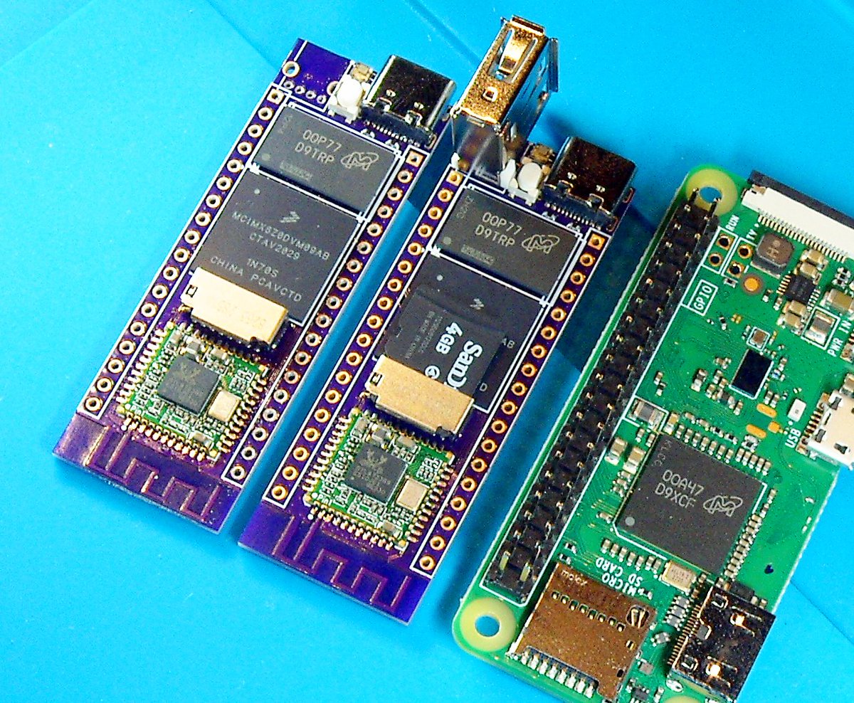
This board uses the $2.68 http://i.MX 6ULZ, a 900 MHz Cortex-A7. This part is specifically designed for smart-speaker-type applications and lacks the LCD/CSI/Ethernet controller found on the other http://i.MX 6ULL parts.
I’ve always wanted to do a small-form-factor embedded Linux breakout board, but it felt silly laying down a beefy part without ethernet or any of those big parallel multimedia interfaces available. The ULZ has none of that, so it’s a guilt-free form factor for the part.
This one supports standard 40-pin SDIO WiFi/BT modules, so you’ll have options for 802.11n or ac, and BT 4.0-5.0. I’m cheap, so I’ve mounted the RTL8723BS on these two.
The biggest reason you’d have to go from 4L to 6L for designs like this is when you have to cram parts together. You don’t need HDI interconnects (since these are still huge-ass 0.8mm-pitch BGAs), but you definitely need internal routing layers.
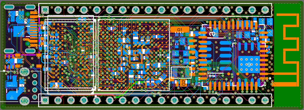
The other reason to go to 6 layers is just ease of routing — this design only took a few hours to throw together. Most of the day was spent fretting in the pinmux tool over which pins to bring out to the headers and what should actually be on the board.
OK, so why would you want this instead of a Pi Zero, ARM9, or Cortex-A5 board? This one has a Cortex-A7 on it, so won’t run into as many compatibility issues with Node.JS, .NET Core, or other software packages useful for IoT projects.
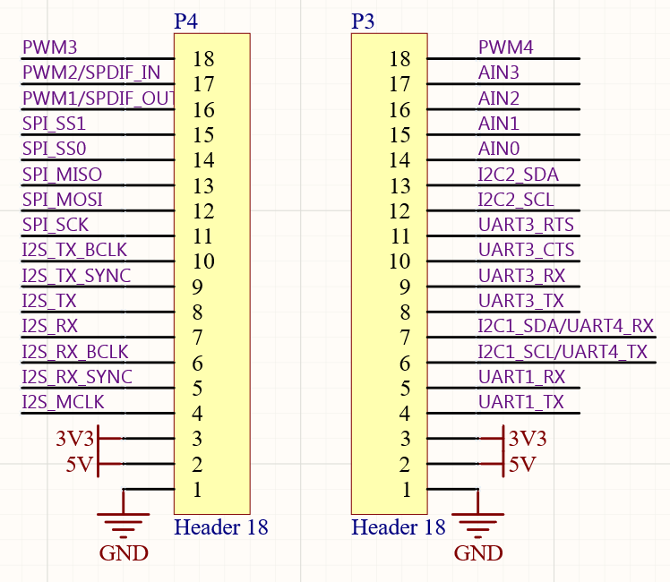
In addition to the onboard WiFi/BT, RGB LED, button, and USB connectors, the board has an I2S interface (with separate signals for RX and TX paths, plus SPDIF), 4 PWM channels, 4 12-bit ADC inputs, SPI, I2C, a console UART, a full UART (good for LTE modems), and a spare UART/I2C.
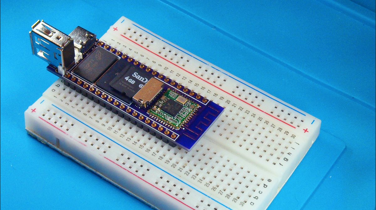
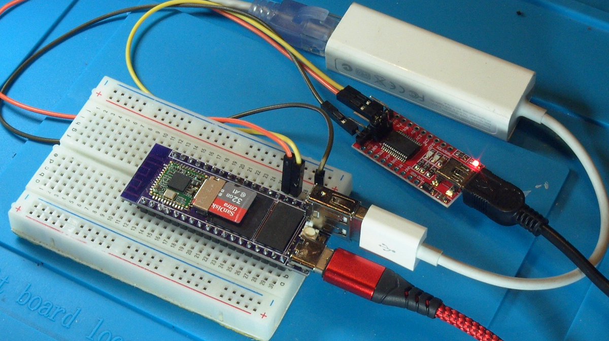
Just did a quick fit on a breadboard to make sure I didn’t have any clearance issues with the thru-hole USB connector. This thing is tiny! And yes, you get two free rows of breadboard pins on either side.
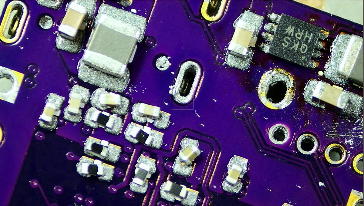
Parts for the bottom side didn’t arrive until today. My 0402 placement is drunk af, but a little heat and these guys pop right into place.

OK, onto bring-up: these buck converters don’t kick on until 2.7V, so you won’t see any current usage before that. Once current was flowing, I measured my 1.35V rail to make sure it wasn’t getting 100% duty-cycled to the input, which can happen if the FB pin isn’t connected


Exposing my 1.35V rail to 2.6V wouldn’t be great, but it’s a lot better than definitely frying it with 5V. Alright, the only other rail, 3.3V, can be verified the same way. Once that’s done, ramp it up to 5V and sanity-check the current consumption across all the assembled boards
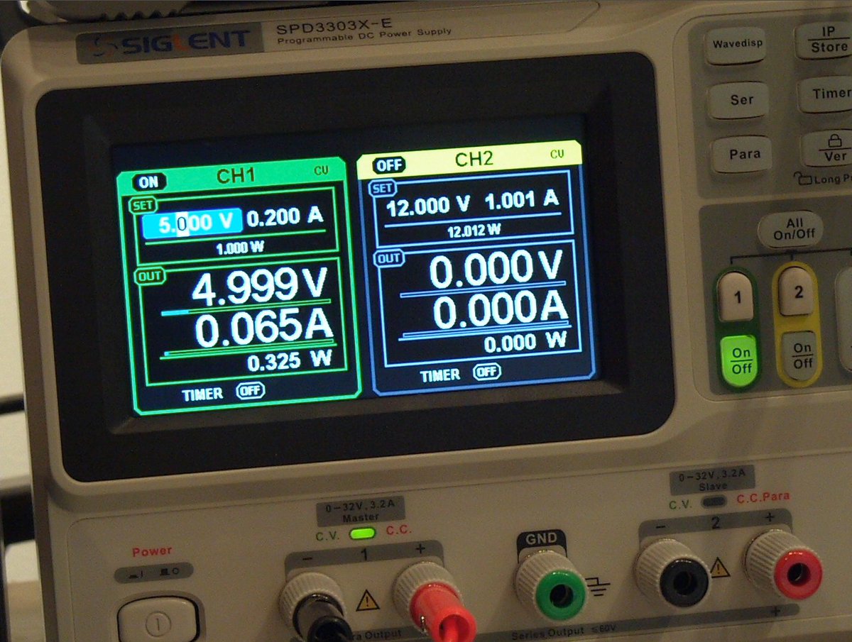
(by the way, ramping up your supplies really slowly can put chips in weird states, so make sure to give it some fresh power to ensure your power sequencing is working)
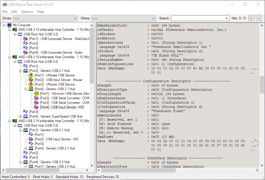
Like many application processors, the iMX6ULZ has a boot ROM that will instantiate as a USB device if attached to a computer. This HID device popped right up when I connected it to my computer, so I know core regulators work, the POR circuitry works, and USB pins aren’t shorted.
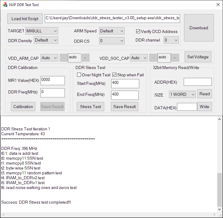
Usually, I’d get U-Boot working at this point, but I was recently reminded that NXP has a Windows GUI app that will stress-test your board over USB. Since PCB CAD is heavily Windows-based, it’s nice that hardware folks can test their board without needing to fire up a Linux VM.
Aaaaaaand it boots! Kind of. I need to get a U-Boot port and device tree going for the board, and there appears to be a weird MMC driver bug in U-Boot right now, so I had to steal a binary from a friend (thanks @EvanHailey!) to get things going. But it’s alive!
OK, I’ve verified enough of this design to feel comfortable pushing it out the door. Here it is!
Since people appear to actually be looking at this, I cleaned up the BOM a bit and added it to the docs. Down to 27 lines, but if you use 10uF caps on all the 0603 pads you’d be down to 25. You could probably get away with 5k1 resistors on all 1-10k spots. down to 23. Not bad!
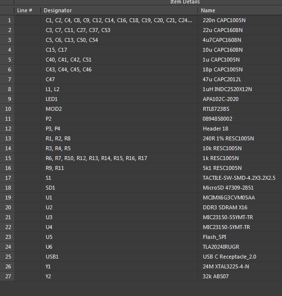
With the 3.3V regulator so close, the 47uF on the MicroSD could become a 10uF. Down to 22 lines. Don’t need an RTC? Then nix Y2. Now at 21 lines. Of course, the board would boot fine without the LED or pushbutton, and I haven’t even mounted the QSPI flash yet. BOM: 18 lines.
The whole “premature optimization” warning that everyone parrots to each other is so tired. I’m a big fan of aggressive BOM optimization early on if there’s a remote chance I’ll be hand-assembling any prototypes. BOM lines kill productivity at every step of the prototype process.
Originally tweeted by ᴊᴀʏ ᴄᴀʀʟsoɴ (@jaydcarlson) on February 2, 2021.
