Greg Davill’s Advent Calendar of Circuits 2020

The talented Greg Davill took on the challenge of designing an average of 1 circuit board design and layout per day for 31 days in December.

Advent Calendar of Circuits 2020

  1. gdpi SYZYGY pod featuring 2x digital video ports
  2. resonance Addon board for card10 to add video output
  3. meiji-led-ring Illuminator to fit around the front of a microscope
  4. pcie_x4 SYZYGY pod creating a PCIe x4 add-in card
  5. icebreaker++ icebreaker FPGA board, upgraded with an ECP5
  6. pcie_x1 SYZYGY pod creating a compact PCIe x1 add-in card
  7. arm-watch New ARM based controller for the Casio CA-53W watch
  8. syzygy-sgmii Gigabit ethernet using an SGMII based PHY
  9. hdmi-si HDMI breakout board
  10. quad-7segment PMOD with a quad 7segment
  11. syzygy-breakout Breakout board for a standard SYZYGY connector
  12. icebreaker++-ram icebreaker FPGA board, upgraded with an ECP5 (+extra RAM)
  13. sd-dummy Dummy SD card to connect to a host system via SDIO
  14. gpdi-serdes GPDI using the serdes
  15. rpi-hq-camera Connector for the Raspberry Pi HQ camera
  16. syzygy-pmod SYZYGY to PMOD adapter
  17. pmod-gnss GNSS PMOD, GPS + Glonass
  18. led-panel Breakout for some White LEDs
  19. syzygy-txr-breakout SYZYGY TXR4 to SMA connectors
  20. syzygy-dual-atto320 SYZYGY to dual Atto320 LWIR sensors
  21. syzygy-rgb888-lcd SYZYGY 5″ 800×480 LCD panel
  22. memory-lcd-wing minimal wing for OrangeCrab
  23. syzygy-flir-tau2 SYZYGY tau2 LWIR core
  24. syzygy-flir-boson SYZYGY boson LWIR core
  25. SCD30-3d-model 3d model for the SCD30 CO2 Sensor
  26. esp32s2-co2-monitor ESP32s2 + Sharp memory LCD + CO2 Monitor
  27. jtag-programmer FT232H based JTAG programmer
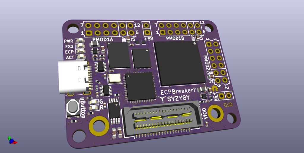
  28. ECPBreaker ECP5 based icebreaker update, FX2 HS USB + SYZYGY
  29. esp32s2-lepton Small ESP32 based thermal camera
  30. esp32s2-breakout ESP32S2 + Sharp memory LCD
  31. syzygy-epc901 SYZYGY breakout with an EPC901 CCD + 50MSps ADC

Greg Davill’s Advent Calendar of Circuits 2020

Helen Remoticon Video: From Zero to ASIC; How to Design in Silicon

Designing your own integrated circuits as a one-person operation from your home workshop sounds like science fiction. But 20 years ago, so did rolling your own circuit boards to host a 600 MHz microcontroller with firmware you wrote yourself. Turns out silicon design isn’t nearly as out of reach as it used to be and…

Remoticon Video: From Zero to ASIC; How to Design in Silicon — Hackaday
Helen Remoticon Video: From Zero to ASIC; How to Design in Silicon

Open Source Pulsed Plasma Thruster

From Michael Bretti of Applied Ion Systems:

AIS-EPPT1 Pulsed Plasma Thruster

The AIS-EPPTPulsed Plasma Thruster an experimental pulsed plasma thruster design aimed at low-cost, easy to manufacture, and simplified propulsion for Cubesats and PocketQubes. This system takes lessons learned from the original AIS-gPPT3-1C Integrated Propulsion Module and further expands its capabilities to attempt to increase fuel capacity, improve ignition, performance, and ultimately lower PPT cost and simplify manufacturing. The highly compact thruster is small enough for integration with PocketQubes, and can be implemented as a single thruster, cluster, or attitude control for Cubesats.

Open Source Pulsed Plasma Thruster

Teensy 16 channel DAC

Teensy creator Paul Stoffregen announced on Twitter:

Today I dusted off a 16 channel DAC PCB I had designed on a whim back in March. Fiddled ’til I found settings to make the ADAU1966A spring to life. It’s generating 16 distinct waveforms!

Here is the OSH Park shared project from Paul:

ADAU1966A Test

So far this PCB has only been tested with the code below. It does produce 16 different waveforms output with the correct frequencies and waveform shapes. The board seems to work, but no other testing has yet been done (or perhaps by the time you’re reading this, maybe this page is old info….)

Sharing this because it was requested on this Tweet. https://twitter.com/insolace/status/1342452185552932864

This board uses the ADAU1966A chip from Analog Devices. Analog Devices also made an older version of this chip, ADAU1966 without the “A”. It is listed as not recommended for new designs. If you search and find the old chip, don’t worry. Just make sure you’re searching for ADAU1966A with the “A”.

Teensy 16 channel DAC

Discrete LEDs Make a Micro Display

Kerry Scharfglass writes about this great project from Alex in Munich (@tinyledmatrix) on the Hackaday blog:

Discrete LEDs Make a Micro Display

Few things excite a Hackaday staff member more than a glowing LED, so it should be no surprise that combining them together into a matrix really gets us going. Make that matrix tiny, addressable, and chainable and you know it’ll be a hit at the virtual water cooler. We’ve seen [tinyledmatrix]’s work before but he’s back with the COPXIE, a pair of tiny addressable displays on one PCBA.

The sample boards seen at top are a particularly eye catching combination of OSH Park After Dark PCB and mysterious purple SMT LEDs that really explain the entire premise. Each PCBA holds two groups of discrete LEDs each arranged into a 5×7 display. There’s enough density here for a full Latin character set and simple icons and graphics, so there should be enough flexibility for all the NTP-synced desk clocks and train timetables a temporally obsessed hacker could want.

But a display is only as good as it’s SDK, right? The COPXIE is actually designed to be a drop in replacement for a different series of tiny LED matrices, the PIXIE by [Lixie Labs]. To complete the effect the COPXIE runs the same firmware and so has the same feature set. Each module (with two displays) can be controlled with just two pins (data and clock), and chains of more than 12 modules (24 displays) can be strung together. Plus there is a convenient Arduino friendly library which makes control a snap.

To build a COPXIE of your own, check out the schematic linked on the Hackaday.io page, and the layout at the OSH Park share link. Note that it seems like [tinyledmatrix] may not have completely validated these boards, but given there are plenty of photos of them working they seem like a safe bet.

Discrete LEDs Make a Micro Display

DIY gauge upgrade for a Porsche

Great DIY automotive project from Evan Li:

BUILDING A QUAD GAUGE FOR A PORSCHE 914

I’ve recently become the co-owner of a 1972 Porsche 914 with a 5.7L LS1 swap. As a result of the shift from air cooled to water cooled, the car required the addition of a gauge for coolant temperature. An oil pressure gauge was also added and the two gauges sat together, mounted on the floor near the shifter. It didn’t look great

DIY gauge upgrade for a Porsche

Hackaday Remoticon: KiCad to Blender PCB Renders

In this workshop, Anool Mahidharia takes the output of KiCad’s VRML export, gets it rendering in Blender, and then starts tweaking the result until you’re almost not sure if it’s the real thing or a 3D model. He starts off with a board in KiCad, included in the project’s GitHub repo, and you can follow along through the basic import, or go all the way to copying the graphics off the top of an ATtiny85 and making sure that the insides of the through-plated holes match the tops.

If you don’t know Blender, maybe you don’t know how comprehensive a 3D modelling and animation tool it is. And with the incredible power comes a notoriously steep learning curve up a high mountain. Anool doesn’t even try to turn you into a Blender expert, but focuses on the tweaks and tricks that you’ll need to make good looking PCB renders. You’ll find general purpose Blender tutorials everywhere on the net, but if you want something PCB-specific, you’ve come to the right place.

Read more…

Hackaday Remoticon: KiCad to Blender PCB Renders

How to make a RPi CM carrier board in KiCad

The wonderful Shawn Hymel has a new video on designing a base board for the new Raspberry Pi compute module:

How to Make a Raspberry Pi Compute Module 4 Carrier Board in KiCad – Part 2 | Digi-Key Electronics

Raspberry Pi released the Compute Module 4 (CM4) in October, which is a single board computer with all of the processing power of the Raspberry Pi 4, but in a tiny form factor! It removes many of the connectors (USB, HDMI, etc.), as the intention is for you to add your own with a custom board and enclosure.

In this series, we’ll show you how to create your own, custom Raspberry Pi CM4 carrier board with KiCad!

How to make a RPi CM carrier board in KiCad