From Jonathan Cohen on Tindie:
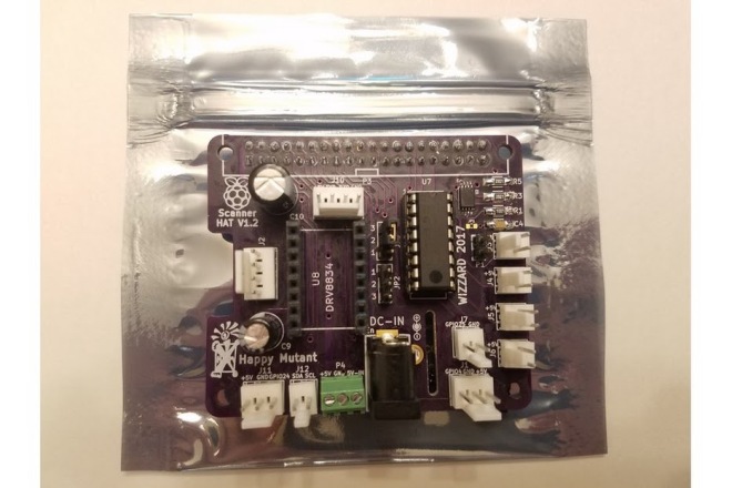
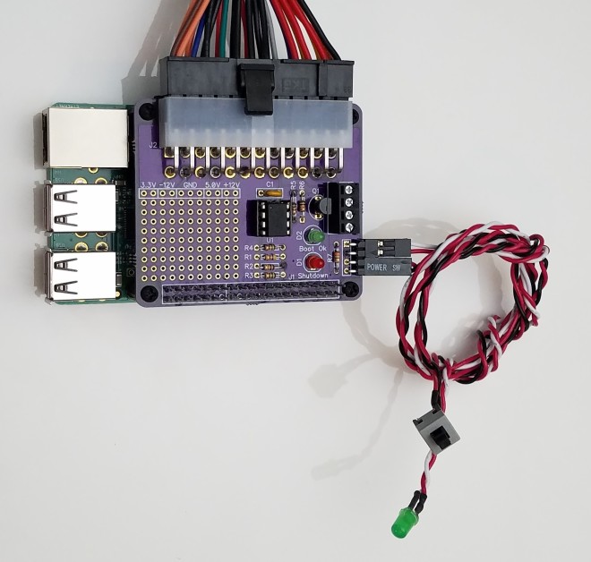
3D Scanner HAT for Raspberry Pi
3D Scanner HAT expansion board interface for Raspberry Pi running FreeLSS on the PICLOP ATLAS FreeLSS


I wanted to make a custom interface for use with the open-source 3D Scanning software, FreeLSS. I was very impressed with the Arduino-based Ciclop scanner and the Raspberry Pi-based Atlas Scanner. Several FreeLSS users merged the two scanner platforms, creating the PiCLOP 3D Scanner. However, there were few changes to the basic PCB design used for the scanner. I wanted to integrate the hardware functionality into a Raspberry Pi HAT format, with the inclusion of extra features for expandability — and who knows, other uses !


What makes it special?
- Conforms to the Pi Foundation specification for HATs !
- 5V power design (only a single voltage) allowing for Pololu low-voltage stepper driver carrier.
- Connections for up to two independent soft-PWM controlled LED light sources.
- I2C interface for OLED displays and light intensity sensors, e.g. TSL2561 or TSL2591.
- Serial communication breakout for console support.
- Additional GPIO signal breakouts for other sensors and devices.
- User-programmable EEPROM ! for auto-configuration and device overlays.
- Standard DC power connector for up to 5V 4A power supply and connections for power switch.
- Over-current protection by poly re-settable fuse.