PiMod Zero: Raspberry Pi Zero RF Video Modulator

We excited to see this Raspberry Pi Zero RF Video Modulator on Crowd Supply:

PiMod Zero

Dust Off That Old TV

PiMod Zero brings old tech back to life by allowing a Raspberry Pi Zero to display color or B&W video – and play audio – on vintage televisions. It provides a super-compact way to watch old movies, play retro games, present digital art, or navigate your operating system using any television that receives standard NTSC broadcasts on VHF channels 2 and 3 (55.25 MHz and 61.25 MHz).

In the past, you would have needed a cumbersome RF modulator box to adapt the HDMI signal from a Pi Zero. Now, with this convenient HAT snapped on top of your Pi Zero, no additional dongles are required. In fact, once the Pi is powered up, the only other cable you need is a piece of coax to connect PiMod Zero to your TV.

Configuring the Raspberry Pi to output composite video and stereo audio to PiMod Zero is extremely simple. Handy scripts and thorough documentation will be available in our GitHub repo.

PiMod Zero: Raspberry Pi Zero RF Video Modulator

Open-Hardware STM32 Firefly BLE Dev Board

Gareth Halfacree writes on Hackster:

PeskyProducts, Tlera Corp Launch Open-Hardware STM32 Firefly Bluetooth Low Energy Dev Board

Available to order as a PCB from OSH Park or a completed unit from Tindie, this compact Arduino-compatible aims to make BLE a cinch.

PeskyProducts and Tlera Corp have designed an open-hardware development board for Bluetooth Low Energy (BLE) projects, built around STMicro’s STM32 microcontroller and boasting full Arduino IDE support: the Firefly BLE.

“This is a small, open source hardware implementation designed to make using and customizing the STM32WB55 easy for everyone,” Tlera Corp explains of the Firefly BLE’s design. “It supports iBeacon, NUS, BlueST protocols as well as standard and custom BLE services and characteristics.

“For several years we have been making use of ST’s STM32L4 family of ultra-low-power MCUs in a variety of applications including development boards, asset trackers, and environmental monitors. Often we include a BMD-350 (nRF52) module for BLE connectivity with smart devices like Android and IOS phones, etc. With the new dual core STM32WB55 MCU, we can now make devices similar in cost, size, and functionality to those we have been but also have the added benefit of embedded BLE connectivity.”

Open-Hardware STM32 Firefly BLE Dev Board

Crowd Supply: connect Peloton bike to third-party apps and fitness watches

Coming soon to Crowd Supply:

Data Fitness Connector (DFC)

The Data Fitness Connector (DFC) data broadcaster is a Bluetooth device that allows Peloton bikes to communicate with fitness watches, head units, and apps—a feature that’s not available on stock Peloton bikes. It reads power and cadence data in realtime, through a cable connected to your bike, and broadcasts them to nearby devices, including those built around non-Peloton platforms like Zwift and Garmin. This allows you to enjoy the built-in functionality of your bike while simultaneously utilizing features and services that depend on third-party platforms.

One of our goals for this project is to make it easier for hobbyists to design and build hardware that interacts with fitness machines, which is why we’re offering a Maker Edition of DFC. Sure, if you’re trying to start the next indoor fitness revolution, you probably have your own hardware team. But what if you just want to crank up the music and cue some heroic lighting when you hit your pace? Or progressively inflate a balloon so you know your workout’s over when it pops? DFC lets you bring your quirky idea to life and take it for a ride on the handlebars.

Or you could do something practical! If you must. Add a dedicated display and use it to chart realtime metrics that Peloton doesn’t display. Or log your raw data offline for the last word in platform independence. Or attach an array of sensors and see how your performance is affected air quality, humidity, and other indoor environmental factors.

Crowd Supply: connect Peloton bike to third-party apps and fitness watches

nRF9160 Feather combines mobile data, GPS and low power

Jared Wolff designed this nRF9160-based board in the Adafruit Feather form-factor featuring cellular connectivity, GPS and low power features:

nRF9160 Feather

The nRF9160 Feather by Jared Wolff (aka Circuit Dojo LLC) is an electronics development board. It features tghe nRF9160 by Nordic Semiconductor. This part is capable of both CAT M1 LTE and NB-IoT for communication with the outside world. It’s compatible with the Zephyr RTOS which is fully baked into Nordic’s nRF Connect SDK. Other toolchains and languages coming soon to a Github repository near you.

nRF9160 Feather combines mobile data, GPS and low power

What Makes A Good Antenna?

From Jenny List on Hackaday:

What Makes A Good Antenna?

It sometimes seems as though antennas and RF design are portrayed as something of a Black Art, the exclusive preserve of an initiated group of RF mystics and beyond the reach of mere mortals. In fact though they have their difficult moments it’s possible to gain an understanding of the topic, and making that start is the subject of a video from [Andreas Spiess]. Entitled “How To Build A Good Antenna”, it uses the design and set-up of a simple quarter-wave groundplane antenna as a handle to introduce the viewer to the key topics.

What Makes A Good Antenna?

Portable Ham Antenna Uses SMD Capacitors

From Al Williams on Hackaday:

Portable Ham Antenna Uses SMD Capacitors

[K6ARK] likes to operate portable, so he puts together very lightweight antennas. One of his latest uses tiny toroids and SMD capacitors to form trap elements. You can see  the construction of it in the video below.

You usually think of toroid winding as something you do when building transmitters or receivers, especially small ones like these. We presume the antenna is best for QRP (low power) operation since the tiny core would saturate pretty quickly at higher power. Exactly how much power you should pass through an FT50-43 core depends on the exact application, but we’ve seen numbers around 5 watts.

Portable Ham Antenna Uses SMD Capacitors

Penguino Feather LoRa dev board

MakerTronika Labs in Azerbaijan created this LoRaWAN capable dev board in Feather form factor:

Penguino Feather 4260 (SAMR34) LoRa Dev-Board

This is a SAMR34 based LoRa/LoRaWAN™ dev-board with all the necessary components for fast prototyping. It’s a successor of my previous Penguino SAMR34 design. The new design uses the RAK4260 module from @RAKWireless and improves on some aspects, such as a USB Type-C, a RGB LED, a user button, battery protection & voltage supervision, and optional flash & per-provisioned secure element IC pads.

Current HW version is v.1.2 and it’s offered in green soldermask (ENIG). All the design files can be found on my GitHub.

From v.1.2 onward the Penguino board also features CH340E USB-to-UART converter to further ease the development.

Penguino Feather LoRa dev board

QRP-Labs Filter Adapter for NanoVNA

Cabe Atwell writes on Hackster about a RF filter adapter was made using some spare parts and lowpass and bandpass filter kits:

nanovna_qrplabs_20_FEE8nQ8TSv

QRP-Labs Filter Adapter for NanoVNA

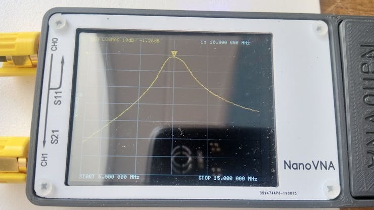
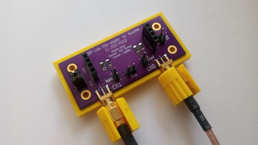
Check out Lex Bolkesteijn’s new project constructing a QRP-Labs filter adapter for NanoVNA with some spare parts and lowpass and bandpass filter kits. The NanoVNA is a tiny handheld Vector Network Analyzer (VNA), which accomplishes both high-performance and portability. Besides working as a vector network analyzer and antenna analyzer, this build utilizes it as a filter tuner.

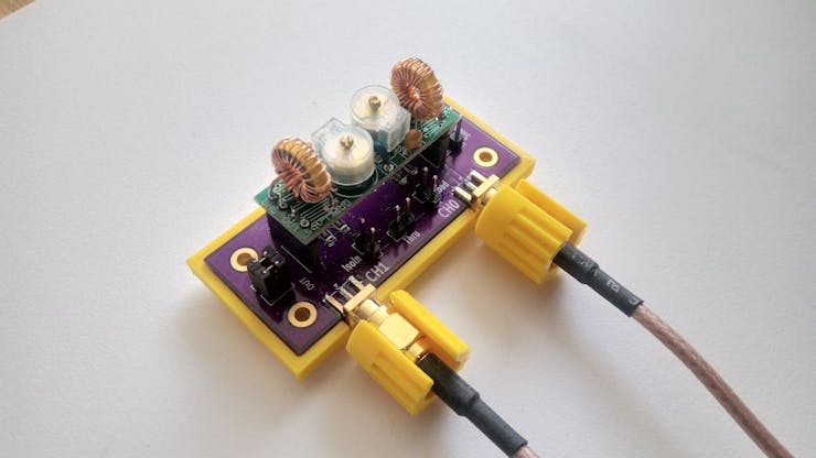
A current work in progress, last updated in mid-June, it was developed using a double-sided PCB, two SMA chassis, and a header cut in two to form a filter holder that enabled the use of the NanoVNA to test and tune the filters as required. The filter kits themselves include the double-sided PCD along with silkscreen, solder mask, and through-hole plating, as well as the capacitors. Both are the same size, and so require no adjustments to the filter holder.

Although the filter has four pins, five holes are drilled in the PCB base of the filter holder using a perforated PCB for spacing. The fifth hole allows for a via to connect the top and bottom layers. With some soldering, the via, SMA chassis parts, and headers are connected to the base. In a few steps that, everything is set up to connect the filter to the NanoVNA.

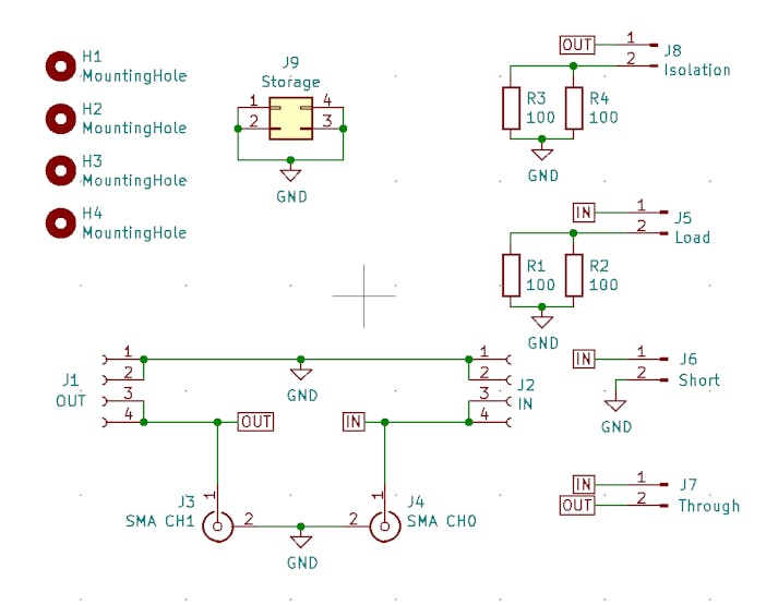
The NanoVNA should be calibrated before use, and in the documented project, this was done with an experimental calibration tool. When calibrating as close as possible to the adaptor, it’s not possible to use the calibration standards. The calibration tool was made with another PCD, with holes drilled for vias and two 100 Ohm SMD 1206 resistors.

A design, complete with CAD files for the casing, is also included for those who are unable to mill PCBs by hand. This uses a 3D-printed casing and custom-ordered PCBs to serve as the adapter. Simplifying the manual work required in the design, even more, the most recent custom PCB ordered includes built-in calibration options. The 3D-printed base looks spiffier than the hand-milled PCBs and requires no additional PCB for calibration.

For anyone interested, the bill of materials, CAD files, and a step-by-step with images are freely available on Bolkesteijn’s blog.

QRP-Labs Filter Adapter for NanoVNA

Build Your Own RF Lab: Scalar Network Analyzer

Whitney Knitter writes on Hackster about a simple scalar network analyzer that can be controlled by a Raspberry Pi for measuring the frequency response of filters and networks:

screen_shot_2020-06-21_at_12_39_16_am_QwvfFybZEx

Build Your Own RF Lab: Scalar Network Analyzer

With the popularity of wireless applications having become such a staple in the hobbyist community, the need for RF testing capabilities in the hobbyist realm has also increased. Anyone familiar with traditional RF test equipment knows that it is expensive. But challenges like this are what bring out the engineering creativity in this community. Steven Merrifield designed and laid out his own simple scalar network analyzer (SNA) using just a few IC chips. SNAs are handy for testing the frequency response of filters or networks.

A scalar network analyzer is used to test the amplitude of a device’s frequency response by outputting a sine wave sweeping over a certain frequency range (bandwidth) then measuring the amplitude of each incremental output frequency.

Thus if you directly connect the sine wave output of an SNA to its measurement input, then it will read a flat line of the same amplitude for each incremental output frequency of the sweep:

When a device is connected to the SNA, the amplitude of the sine wave at each frequency after going through the device will reflect the device’s frequency response over that bandwidth.

Merrifield’s design accomplishes an SNA’s functionality via implementation of a DDS Synthesizer chip, an ADC, and a logarithmic amplifier chip. The AD9850 DDS is responsible for outputting the sweeping sine wave while the AD8307 logarithmic amplifier conditions the signal input into the SNA for the log of the signal’s envelope before passing it on to the ADC for digitizing. A second AD8307 also conditions the output of the DDS and outputs it to a second channel of the ADC so that it can be used in software for compensation of any variations on the DDS’s output due to the effects of various loads of devices being tested.

The ADC outputs its digital measurements via an I2C interface to a GPIO header that matches the Raspberry Pi’s GPIO header pinout, but any desired MCU or FPGA could be used. The source code Merrifield wrote is in C, making it easy for porting across different platforms.

Check out Merrifield’s project logs here. He linked his PCB layout on OSH Park if you’re interested in ordering it and putting one of these together for your own lab!

Build Your Own RF Lab: Scalar Network Analyzer

QRP-Labs filter adapter for NanoVNA

nanovna_qrplabs_06

QRP-Labs filter adapter for NanoVNA

I had a few QRP-labs lowpass filters and bandpass filters kits laying around and because I had nothing better to do this afternoon, I fired up the soldering station and assembled them. After that they need to be tested and tuned.

Owning a NanoVNA for a few months now (and hardly use it because for antenna stuff i use my RigExpert AA-600), I decided to use the NanoVNA for tuning the filters. So from some pieces out of my junkbox (a piece of double sided pcb, 2 sma chassis and a header cut in 2) I build this simple filter holder allowing me to test and tune the filters to my requirements.

Adding the 3D printed base plate, hooking it with my NanoVNA.

nanovna_qrplabs_06

Doing the calibration routine.

nanovna_qrplabs_06

And ready for testing.

nanovna_qrplabs_06

As expected like the previous design. But now no aditional PCB for calibration.

nanovna_qrplabs_06

Can only say that the purple on yellow looks cool 🙂

For those who want a adapter, checkout my ForSale page.

QRP-Labs filter adapter for NanoVNA