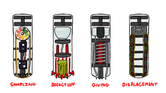
This summer, I am once again diving into designing mechanical personality quirks. I’ll be investigating new and exciting ways for my robot, NoodleFeet to interact with the world. This time, my focus is the wet, tingly and preferential aspect of TASTE.
From now until the end of August, my goal is to produce four different tasting modules that each demonstrate some aspect of sampling or preference. You could think of them as the “four tasters of the apocalypse”
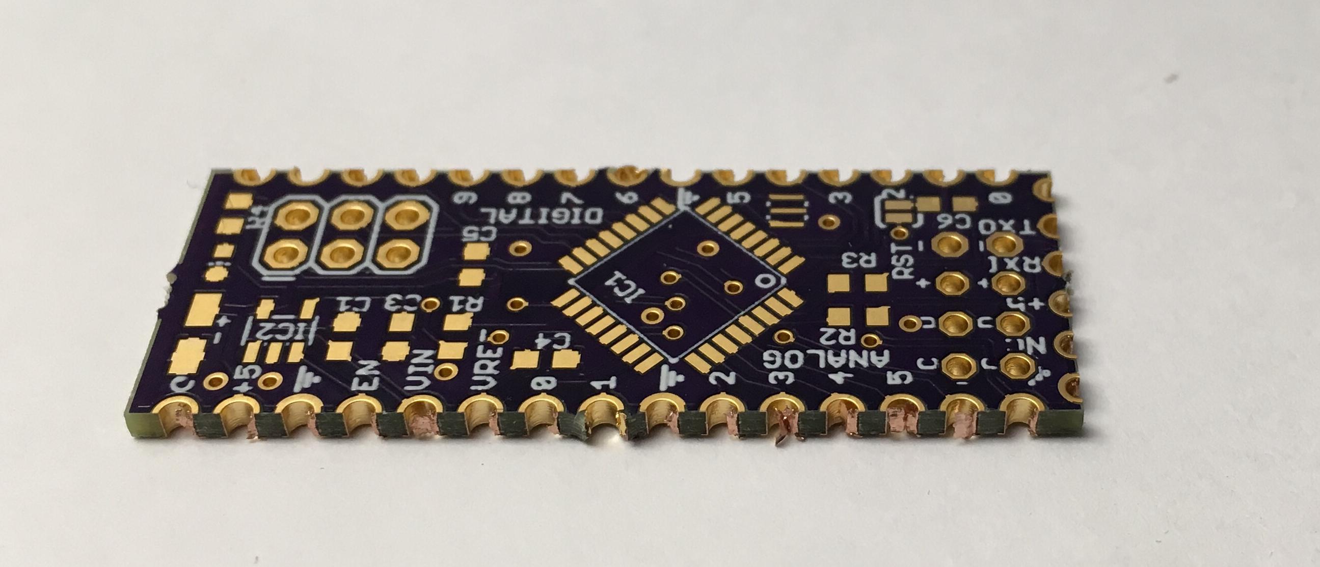
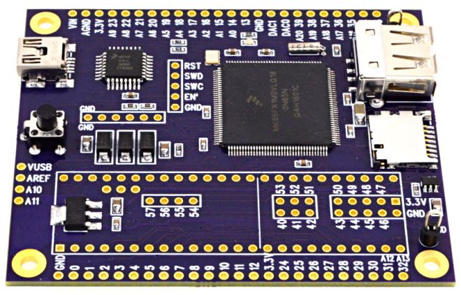
Castellations are small plated edges, typically used for making circuit boards into small PCB modules. These are often seen on wireless modules, such as the ESP8266-12E.
While we don’t offer full support for castellations, they can be fabricated if you don’t mind a few minutes of rework and verification of the PCBs.
Design Considerations
It’s helpful to include a fallback hole near the edge. The ESP8266-12E boards, are a great example here. The extra via allows easy connecting of wires for rework, and makes it easy to salvage a module if the fabricated PCB doesn’t turn out perfectly.
Castellations are simple to call out in most design tools. Simply include a via on the PCB, so the board outline goes through it.
However, due to our panelization process, the castellated vias must be indicated with round pads for copper and stop mask. The pads must also not extend more than 40 mil from the board edge. Square pads or pads that extend far beyond the edge will be trimmed, and the via will not be plated.
It’s also helpful to use a 10 mil wide line for the board outline. With our milling tolerance of 5 mil, this provides a good visual indicator of where the physical board edge might be. The fabricated edge can be anywhere within that line. This is very helpful for fine-pitch castellations with smaller holes.
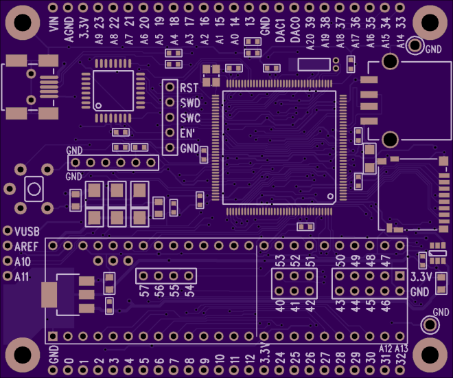
Callout as seen in a design tool
Rectangular castellations can be made by using vias with round pads as noted above, and adding overlapping rectangular SMD pads. Since these pads are inside the board outline, they will not be trimmed, and will provide additional area for soldering (see below for example).
Cleaning up the final boards
We make a best-effort to minimize support tabs on castellated edges, but it sometimes happens. In these cases, you’ll need to file the tab off of your edge.
Additionally, the via plating may not be fully removed during the milling process. In some cases it’s smashed next to the edge, where it can cause unwanted connectivity between vias. In others, it’s smashed inside the via, where it will prevent good solder flow. A fine point file or hobby knife will help remove excess plating.
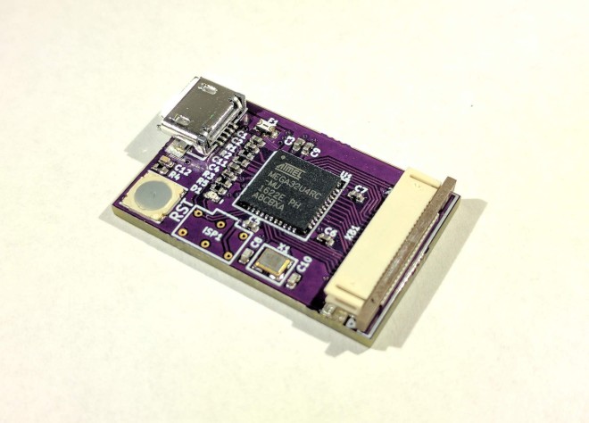
An unreworked castellated PCB, with visible plating stubs
Another version, with tabs on castellated edge and modifications for rectangular pads
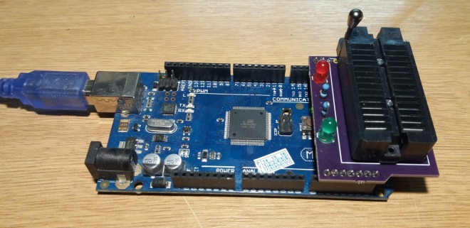
Some time ago, I wrote about my DIY EEPROM programmer driven by an Arduino Mega. It’s a very simple, low-tech project … but has attracted a consistently-high number of visitors to the site and is something I use several times a week.
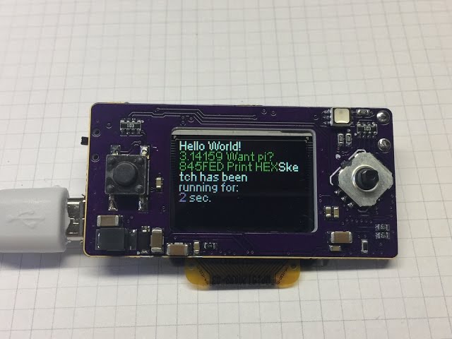
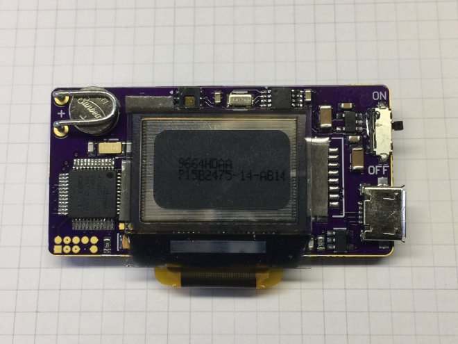
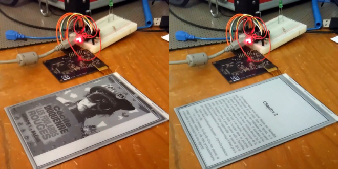
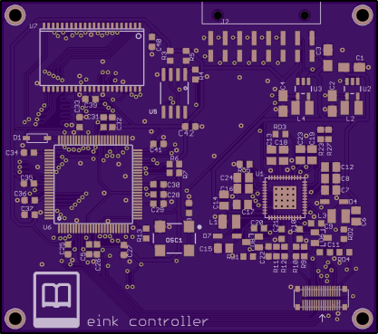
E-ink displays are awesome. Humans spent centuries reading non-backlit devices, and frankly it’s a lot easier on the eyes. But have you looked into driving one of these critters yourself? It’s a nightmare. So chapeau! to [Julien] for his FPGA-based implementation that not only uses our favorite open-source FPGA toolchain, and serves as an open reference implementation for anyone else who’s interested.
Watch the E-Ink controller in action:
Design files and source code are available on GitHub:
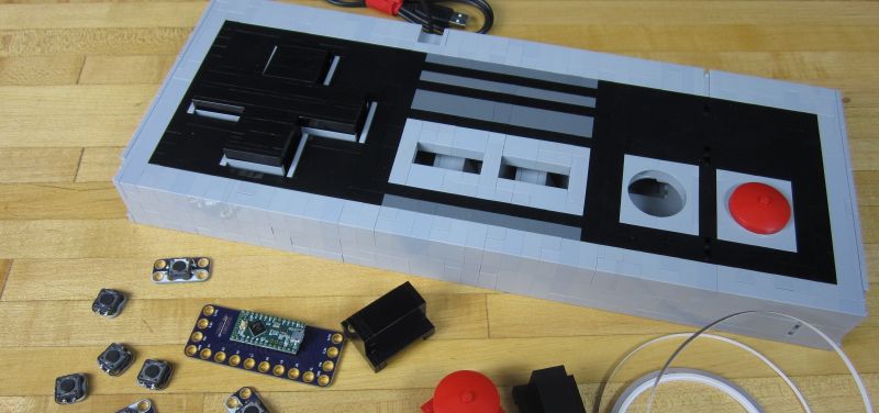
[BrownDogGadgets] built a giant NES controller out of LEGO. The controller is designed in LEGO Digital Designer, which lets you create a virtual model, then get a full list of parts which can be ordered online.
The electronics are based on a Teensy LC programmed to appear as a USB keyboard, and the buttons are standard push buttons. The insides are wired together with nylon conductive tape. LEGO was an appropriate choice because the Teensy and switches are built on top of LEGO compatible PCBs, so components are just snapped in place. The system is called Crazy Circuits and is a pretty neat way to turn electronics into a universal and reusable system.
Here is the controller in action:
Design files and source code for Crazy Circuits modules and projects are available on GitHub: