Hackaday Belgrade: Sophi Kravitz’s Blimp Army

From  on Hackaday:

Hackaday Belgrade: Sophi Kravitz’s Blimp Army

Building things that fly is hard. The constraints on small, battery powered, radio-operated gear already presents a challenge, but adding weight, balance, and aerodynamic constraints takes it to a whole new level. Sophi Kravitz rises to the occasion and discusses each challenge of building a blimp from start to finish in her presentation at the 2018 Hackaday Belgrade conference.

sophi-blimp-blimp.jpg

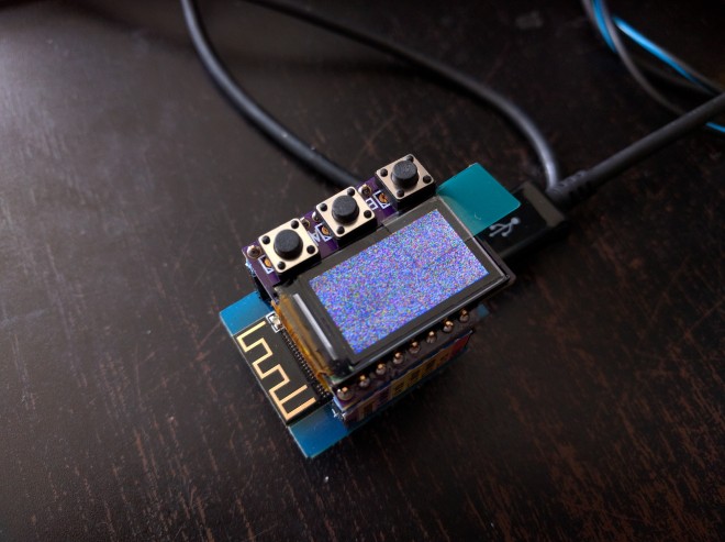
One of the pleasures of writing for Hackaday comes through the incredible array of talent and experience to be found among our colleagues. We all do our own work, but one is humbled by that which flows from the benches of those one works alongside. Just such a project is the Remote Control Mini Blimp from our colleague Sophi Kravitz. It’s a game involving an obstacle course and a set of remote-controlled blimps. The challenges in such an endeavour have been pushing the limits of what is possible with off-the-shelf components.

sophi-blimp-pcbs.jpg

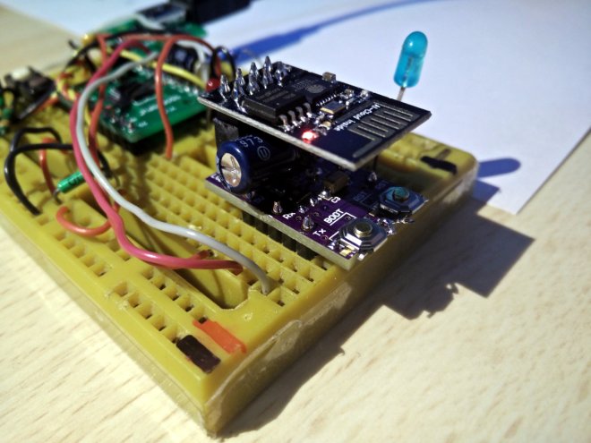
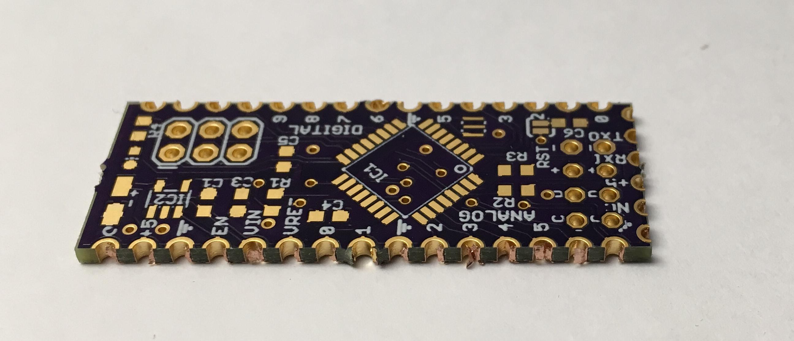
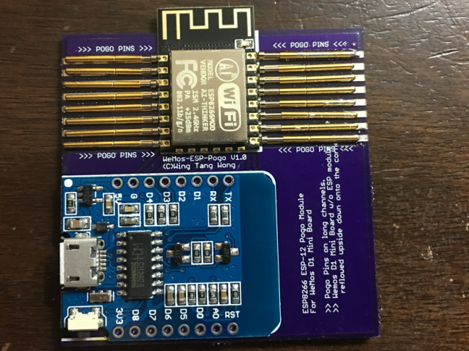
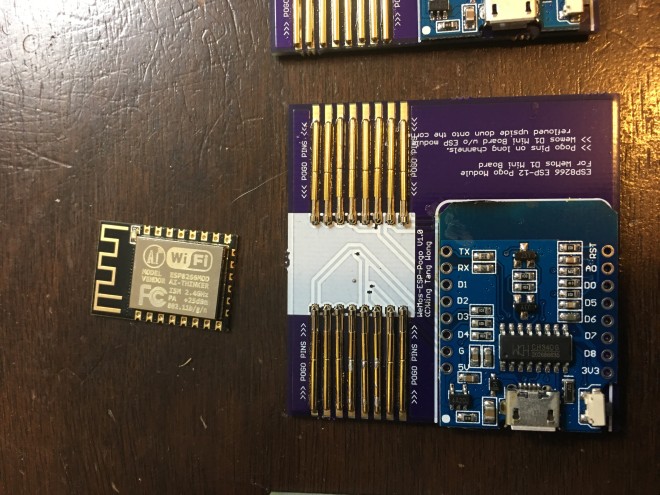
So after a series of versions, she had a PCB with left and right motors on two arms and a lift motor pointing downwards, which she suspended beneath the helium bag. Her controllers are simple enough 3D-printed joystick housings, with another ESP8266 within. The blimp ESP8266 forms a wireless network to which the controller connects.

Quote

ESP8266 Power Switch

9f1b7d6c82f7723494f75bccf80b69b4bb7c1bed

ESP8266 Power Switch

The DomCo Electronics, Inc. ESP8266 AC Power Switch is everything you need to get started with controlling AC mains from an ESP8266. We know dealing with AC can be intimidating for people at times and we wanted to simplify the process of making your own IoT device.

Everything you need to control a 100-240VAC 50/60Hz load is built right onto the board. Simply solder on a power lead and socket of your choice to the Power Switch and the on-board code can get you up and started in minutes. (We have a USA power tail and socket in the optional extras below.) No more needing to wire up an ESP board, a Wall wart, an IoT Power Relay (Power Tail), and a bunch of wires just to control your light or coffee maker.

ESP8266 Power Switch

OSHWi Octopus Badge by Gustavo Reynaga

Alex Glow of Hackster.io takes a look at the OSHWi octopus badge designed by Gustavo Reynaga:

Screenshot from 2017-12-23 09-39-22.png

The design files and source code are available on GitHub:

hulkco/oshwi_2017

GReynaga has shared the board on OSH Park:

001_Hackster_Rev1.kicad_pcb

Oshwi Badge HACKSTER Version Rev 1


3eb6bc329e2a6b344b29db05cb1c8f17

Order from OSH Park

OSHWi Octopus Badge by Gustavo Reynaga

LAMEBOY: another ESP12 handheld

davedarko designed this portable ESP12 project with battery charging and power muxing:
3908671505908224547 (1)

LAMEBOY – another ESP12 handheld

Ever since Nokia 3310 / 5110 display board I’ve wanted to slap on an ESP module and some buttons to make a nice little portable handheld. Now with some googling and checking out other projects how they get their stuff done and a bit time on hand while on vacation I’m using every spare minute to work on this PCB. There are some minor things I’m not sure about that need testing, but the general concept is clear. 
LAMEBOY: another ESP12 handheld

Help gamaral’s Cancer Treatment

If you’ve enjoyed Guillermo Amaral’s electronics projects such as the Canon DSLR WiFi RemoteRaspberry Pi PSUUARTMatic 3000+, Keypad Submodule and many more, then please consider giving to his cancer treatment fund:

Gamaral’s Cancer Treatment

I’ve unfortunately had to flip the bill for my two past surgeries and my on going cancer treatment… and as you can imagine, I’m running out of cash.

If you like my content and/or have found my published projects interesting or useful, please consider sending me some spare change and I’ll be ever so grateful.

Here are couple great project videos by Guillermo on YouTube:

Help gamaral’s Cancer Treatment

Wemos D1 Mini Breakout for an ST7735 Display

Radomir Dopieralski has created this breakout board to make it easier to slap a popular ST7735 module on top of a Wemos D1 Mini:

8571081501668647022.jpg

D1 Mini Breakout for an ST7735 Display

There is a number of options you have for display shields for the D1 Mini: there is the nice OLED shield, there is a shield with a single WS1228B neopixel, there is the #D1 Mini Matrix Shield I’m still working on. But there is no high-resolution color display you could just slap on it. This “shield” doesn’t really deserve the name, it’s just a simple breakout board that connects the ST7735 display module with the SPI pins of the D1 Mini, and adds a trim pot for brightness control.

4514121484133413329.png

To save some pins, the CS pin is hardwired to GND, and the A0 pin is connected to MISO. That means you can’t connect other SPI devices while this is in, but that’s a rare enough case for me to care. It uses four GPIOs total, from GPIO12 to GPIO15. The backlight is connected to the 5V supply (to not strain the on-board 3V3 regulator) through a trim pot, so you can adjust brightness.

I used alternating holes for the module’s header, so that with some luck you should be able to plug in the module directly, without soldering a female pin header there — that should also save some space.

Wemos D1 Mini Breakout for an ST7735 Display

Hackaday: BBSing with the ESP8266

Modems have been around for longer than the web, and before we had Facebook we had the BBS scene. Somewhat surprisingly, people are still hosting BBSes, but have fun finding a landline these days. [Blake Patterson] is one of the leading aficionados of retocomputers, and recently he took it upon himself to review an interesting new…

via BBSing with the ESP8266 — Hackaday

Hackaday: BBSing with the ESP8266

Wireless Terminal Over ESP8266

From debug messages to the fundamental ‘hello world’, serial communication does it all over three little wires. Now imagine being able to cut the cord to your next microcontroller project and use your phone as a VT100 terminal. This was the premise of [Ondřej Hruška]’s Wireless Terminal Project where he took an ESP8266 and added an in-browser terminal emulator which can be accessed…

via Wireless Terminal Over ESP8266 — Hackaday

assembled-on-bb.jpg

Wireless Terminal Over ESP8266

Castellated Edges

Castellations are small plated edges, typically used for making circuit boards into small PCB modules. These are often seen on wireless modules, such as the ESP8266-12E.

While we don’t offer full support for castellations, they can be fabricated if you don’t mind a few minutes of rework and verification of the PCBs.

Design Considerations

It’s helpful to include a fallback hole near the edge. The ESP8266-12E boards, are a great example here. The extra via allows easy connecting of wires for rework, and makes it easy to salvage a module if the fabricated PCB doesn’t turn out perfectly.

ESP2866-12E
ESP2866-12E, available at Adafruit.com

Indicating in the design file

Castellations are simple to call out in most design tools. Simply include a via on the PCB, so the board outline goes through it.

However, due to our panelization process, the castellated vias must be indicated with round pads for copper and stop mask. The pads must also not extend more than 40 mil from the board edge. Square pads or pads that extend far beyond the edge will be trimmed, and the via will not be plated.

It’s also helpful to use a 10 mil wide line for the board outline. With our milling tolerance of 5 mil, this provides a good visual indicator of where the physical board edge might be. The fabricated edge can be anywhere within that line. This is very helpful for fine-pitch castellations with smaller holes.

Callout as seen in a design tool

Rectangular castellations can be made by using vias with round pads as noted above, and adding overlapping rectangular SMD pads. Since these pads are inside the board outline, they will not be trimmed, and will provide additional area for soldering (see below for example).

Cleaning up the final boards

We make a best-effort to minimize support tabs on castellated edges, but it sometimes happens. In these cases, you’ll need to file the tab off of your edge.

Additionally, the via plating may not be fully removed during the milling process. In some cases it’s smashed next to the edge, where it can cause unwanted connectivity between vias. In others, it’s smashed inside the via, where it will prevent good solder flow. A fine point file or hobby knife will help remove excess plating.

An unreworked castellated PCB, with visible plating stubs
Another version, with tabs on castellated edge and modifications for rectangular pads
Castellated Edges

ESP8266 Pogo Jig Programming Board

We like the novel orientation of pogo pins that Wing Tang Wong used in this board design:

screenshot-from-2017-02-28-12-59-47

ESP8266 Pogo Jig Programming Board

Upcycles D1 Mini Wemos board to create a USB connected ESP8266 Pogo pin jig

2034481488075526204.JPG

This is a board designed to take a WeMos D1 Mini board(with the ESP module removed) and use it as a USB interface with built-in reset/flash functionality for bare ESP8266 modules similar to the ESP-12 units.

The design files are available on GitHub:

github ESP8266 Programming D1 Mini Pogo Jig V1

ESP8266 Pogo Jig Programming Board