Open Laptop Soon to be Open For Business

How better to work on Open Source projects than to use a Libre computing device? But that’s a hard goal to accomplish. If you’re using a desktop computer, Libre software is easily achievable, though keeping your entire software stack free of closed source binary blobs might require a little extra work. But if you want a laptop, your options are few indeed. Lucky for us, there may be another device in the mix soon, because [Lukas Hartmann] has just about finalized the MNT Reform.

Since we started eagerly watching the Reform a couple years ago the hardware world has kept turning, and the Reform has improved accordingly. The i.MX6 series CPU is looking a little peaky now that it’s approaching end of life, and the device has switched to a considerably more capable – but no less free – i.MX8M paired with 4 GB of DDR4 on a SODIMM-shaped System-On-Module. This particular SOM is notable because the manufacturer freely provides the module schematics, making it easy to upgrade or replace in the future. The screen has been bumped up to a 12.5″ 1080p panel and steps have been taken to make sure it can be driven without blobs in the graphics pipeline.

via Open Laptop Soon to be Open For Business — Hackaday

Quote

Build a DMX FeatherWing to Control Lights with a Feather M0

Glen Atkins writes about his latest project:

cover-photo-one

This project uses an Adafruit Feather M0 Basic Proto board to control a group of Color Kinetics or other RGB light fixtures using the DMX-512 protocol. We’ll build a DMX-512 interface FeatherWing then connect it to the Feather M0 using a Particle Ethernet FeatherWing. Once the hardware is built and assembled, we’ll write software with a web-based GUI to generate RGB lighting effects and control the attached RGB lights using the DMX protocol. By modifying the software on the Feather M0, different effects can be generated and added to the web-based GUI.

Required Materials

The materials required for this project are:

The DMX FeatherWing

dmx-featherwing-2

The photo above shows the assembled DMX FeatherWing. The next few sections are dedicated to describing and building the DMX FeatherWing hardware.

Circuit Design and Schematic

DMX-512 FeatherWing schematic.

To make sure everything conformed to the FeatherWing form factor, I started with the Eagle design for the Adafruit Power Relay FeatherWing. I deleted everything from the schematic and board except for the FeatherWing symbol and dimension lines. The FeatherWing symbol includes the board outline layer and the holes for the 0.1″ pitch, 0.025″ square post headers that connect the FeatherWing to other boards. I saved this as a new file then started my design.

Build a DMX FeatherWing to Control Lights with a Feather M0

The Newbie’s Guide To JTAG

This JTAG primer will get you up to snuff on snarfing, and help you build your reverse engineering skills.

Whatever your motivation for diving into reverse engineering devices with microcontrollers, JTAG skills are a must, and [Sergio Prado]’s guide will get you going. He starts with a description and brief history of the Joint Test Action Group interface, from its humble beginnings as a PCB testing standard to the de facto standard for testing, debugging, and flashing firmware onto devices. He covers how to locate the JTAG pads – even when they’ve been purposely obfuscated – including the use of brute-force tools like the JTAGulator. Once you’ve got a connection, his tutorial helps you find the firmware in flash memory and snarf it up to a file for inspection, modification, or whatever else you have planned.

via The Newbie’s Guide To JTAG — Hackaday

Quote

ToorCamp call for papers

IMG_20200224_111054

Call For Papers ReleasedWe’re now accepting talk submissions for ToorCamp! You have until April 20th to submit your talk to be considered by our esteemed review panel. We’re looking forward to seeing what you all have been working on!

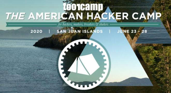
ToorCamp, the American hacker camp, first “launched” at the Titan-1 Missile Silo in Washington State in 2009. The second and third ToorCamp happened in 2012 and 2014 on the beautiful Washington Coast. For the past 2 events (2016 and 2018) and upcoming 2020 are now at the Doe Bay Resort on Orcas Island, WA and are looking for groups to participate. Show off your crazy projects you’ve been working on, bring some ideas you want to hack on with the other technology experts that will be showing up, organize a campsite with all of your friends and show how awesome your group is, or just see what all the other groups are up to. It’s up to you! Either way, we’d like to show that the US can throw down as much as the European hacker camps (CCC CampHAR, etc) so this is your invitation to come!

ToorCamp call for papers

CircuitBrains Deluxe packs CircuitPython into 1 square inc

Kevin Neubauer designed this tiny module that makes it easy to add CircuitPython to a project:

CB-Deluxe-Diagonal_800x800

CircuitBrains Deluxe

CircuitPython on an ARM Cortex M4 in almost 1 square inch! This “Just Add Solder” castellated module is perfect for incorporating into your own project. The CircuitBrains Deluxe board footprint is small enough to fit into narrow spaces and wearable projects.

Rolling your own microcontroller board is time consuming. You have to make sure your design has proper power, decoupling, flash storage, and clock. Then you source all of the parts. After that you lay out the PCB and have it fabricated. When the PCB and parts arrive, you have to deal with finicky small-pitch surface mount assembly. Finally, you need to download the sources for the UF2 bootloader and CircuitPython and define your board, compile, and flash. CircuitBrains Deluxe aims to save makers and hackers some time & frustration. Using it in your project is as simple as importing the footprint libraries, adding those libraries to your schematic and layout (along with your USB port of choice), and soldering it on once your board arrives.

Kevin is aiming to launch a Crowd Supply campaign soon:

https://twitter.com/kevinneubauer/status/1231261132041703426

CircuitBrains Deluxe packs CircuitPython into 1 square inc

Software Defined Everything with Mike Ossmann and Kate Temkin


Software defined radio has become a staple of the RF tinkerer, but it’s likely that very few of us have ever taken their software defined toolchain outside the bounds of radio. It’s an area explored by Mike Ossmann and Kate Temkin in their newly published Supercon talk as they use GNU Radio to do some things that you might find unexpected.

For most people, a software defined radio is a device. An RTL-SDR dongle perhaps, or the HackRF that a popular multi-tool for working in the radio frequency realm. But as they explain, the SDR hardware can be considered merely as the analogue front end, being just the minimal analogue circuitry coupled with a digitiser. The real software-defined part comes — as you might expect — in the software

Kate and Mike introduce GNU Radio Companion — the graphical UI for GNU Radio — as their tool of choice and praise it’s use as a general purpose digital signal processing system whether or not that includes radio. Taking their own Great Scott Gadgets GreatFET One USB hackers toolkit peripheral as an input device they demonstrate this by analysing the output from a light sensor. Instantly they can analyse the mains frequency in a frequency-domain plot, and the pulse frequency of the LEDs. But their bag of tricks goes much deeper, exploring multiple “atypical use cases” that unlock a whole new world through creative digital signal processing (DSP).

via Software Defined Everything with Mike Ossmann and Kate Temkin — Hackaday

Quote

Screaming LM386: An Audio Amplifier with PCB Art

Beautiful project from Frank Milburn on element14:

Intro_Cartoon

Screaming LM386: An Audio Amplifier with PCB Art

I decided to give PCB art a try and will be basing my attempt on methods described by Andrew Sowa.  Andrew uses Adobe Illustrator for the art work and KiCad for the PCB design.  I will also use KiCad but will use my trusty pre-subscription version of Photoshop for the artwork.  Inkscape is another possibility.  Andrew’s process is described in this video from which my work is derived.  The detail behind many of the steps won’t be described in this post – watch the video for that.

The goal is to take a photograph, painting, etc. and place it on a PCB using the FR4, copper layer, solder mask, and silk screen to make the palette.  My PCB will feature the famous work by Edvard Munch, The Scream which has always fascinated me.  So, how to turn a masterpiece into a PCB facsimile?

Screenshot from 2020-02-20 12-40-07

Palette

The limited palette is a challenge.  For this exercise the focus will be on the central figure in order to reduce board size (and thus cost) of the experiment.  The OSHPark purple solder mask will hopefully give the dark colors desired.  Andrew also used OSHPark in his example, and helpfully provided a palette which has been modified here to help describe how the layers translate to color and are stacked for conversion in KiCad.

Palette

There is a shared project for the board:


Screenshot from 2020-02-20 12-35-07

And watch it on YouTube:

Screaming LM386: An Audio Amplifier with PCB Art