Join us on Wednesday, February 19 at noon Pacific for the Open-Source Neuroscience Hardware Hack Chat with Dr. Alexxai Kravitz and Dr. Mark Laubach!
There was a time when our planet still held mysteries, and pith-helmeted or fur-wrapped explorers could sally forth and boldly explore strange places for what they were convinced was the first time. But with every mountain climbed, every depth plunged, and every desert crossed, fewer and fewer places remained to be explored, until today there’s really nothing left to discover.
Unless, of course, you look inward to the most wonderfully complex structure ever found: the brain. In humans, the 86 billion neurons contained within our skulls make trillions of connections with each other, weaving the unfathomably intricate pattern of electrochemical circuits that make you, you. Wonders abound there, and anyone seeing something new in the space between our ears really is laying eyes on it for the first time.
But the brain is a difficult place to explore, and specialized tools are needed to learn its secrets. Lex Kravitz, from Washington University, and Mark Laubach, from American University, are neuroscientists who’ve learned that sometimes you have to invent the tools of the trade on the fly. While exploring topics as wide-ranging as obesity, addiction, executive control, and decision making, they’ve come up with everything from simple jigs for brain sectioning to full feeding systems for rodent cages. They incorporate microcontrollers, IoT, and tons of 3D-printing to build what they need to get the job done, and they share these designs on OpenBehavior, a collaborative space for the open-source neuroscience community.
Join us for the Open-Source Neuroscience Hardware Hack Chat this week where we’ll discuss the exploration of the real final frontier, and find out what it takes to invent the tools before you get to use them.
Our Hack Chats are live community events in the Hackaday.io Hack Chat group messaging. This week we’ll be sitting down on Wednesday, February 19 at 12:00 PM Pacific time. If time zones have got you down, we have a handy time zone converter.
Month: February 2020
Open Hardware Summit 2020 schedule announced
Here is the exciting schedule for the Open Hardware Summit on March 13th in NYC:


Be sure to buy tickets before they are sold out!
DIY Dispenser Places Solder Paste Without The Mess
When doing surface-mount assembly you can certainly use a soldering iron in the traditional way, but it’s far more convenient to cover the pads with solder paste, place the components, and bake the board in a reflow oven. If you’re lucky enough to have a precut stencil this can be done in one go, otherwise a tiny blob of paste must be laboriously placed on each pad by hand. [Kevarek] has made this a bit easier by designing a low-cost handheld solder paste dispenser.
via DIY Dispenser Places Solder Paste Without The Mess — Hackaday
Trash Dove Badge by Angela Sheehan
Angela Sheehan has made a beautiful LED badge based on Syd Weiler’s Trash Dove sticker:
An LED badge I created as a Valentine gift for my partner. The artwork is a rendering of a sticker we often send each other in conversation on messenger.I had fun using this project as a way to gain more practice in AutoDesk EAGLE.
The first thing I did was draw a simplified rendering of the artwork in Illustrator with a condensed palette. The original artwork uses a few different shades of color.
Luckily, OSHPark’s signature purple solder mask, ENIG, and white silk were already pretty good matches for the original sticker palette, so I just needed to make a few adjustments.
I decided on three tones of purple created by:
- Mask over FR4 for the back bird (darkest purple)
- Mask over copper for the front bird’s wing and head (lightest purple)
- Mask over copper stripes for the front bird’s body (mid purple)
I used silk to define some details and for the back bird’s head, and exposed copper for the orange yellow parts of the original artwork.
The heart I left open to backlight with a red LED.
Hardware Happy Hour (3H) Berlin on Feb. 20th
If you are near Berlin next Thursday, February 20th, then check out this social gathering of electronics enthusiasts: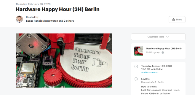
Hardware Happy Hour (3H) Berlin
We will be returning to the Lovelite bar this time.
Please bring your latest project with you! Anything you’re working on, electrical, mechanical or software works! We want to see the stuff that you’re interested in!
Lovelite will open at 6pm and we will officially start at 7pm.
https://www.meetup.com/3HBerlin/events/268451851/
Follow Drew Fustini (@pdp7) for updates!
PCB Geneva Wheel
Sam Ettinger is trying to recreate the classic Geneva Wheel mechanism with circuit boards and is looking for suggestions to improve the mechanism:
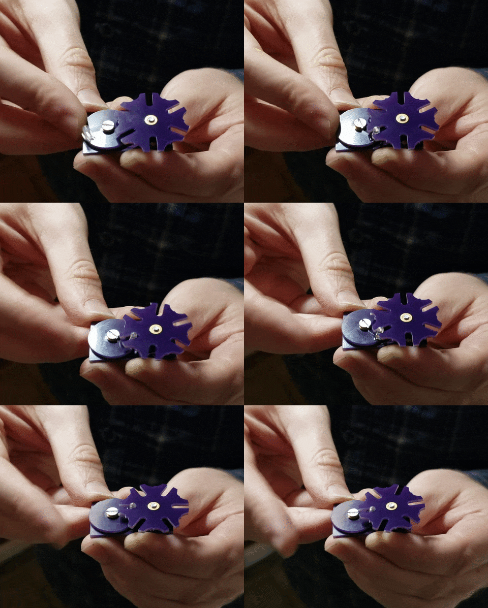
The Geneva drive is a classic way to convert continuous rotary motion into intermittent rotary motion. Usually, homemade demonstrations are done with 3d-printed parts, but I wanted to try incorporating a circuit.
The theory of operation is simple: An LED acts as the “pin” that pushes the slotted Geneva wheel along. Either a 5mm RGB LED, or a 3mm single-color LED for the proof-of-concept. A spacer underneath the Geneva wheel periodically closes or breaks a connection that then goes to the LED cathode(s).
Does it work? Nope! Well, not yet at least. I may try ordering the boards again, with no soldermask around the contacts. But I’m in no hurry.
Let me know if you have ideas or suggestions! Should I put little solder daubs on the exposed traces, or will that create high/low spots and make things worse?
Open Book: On How To Get There From Here
Joey Castillo writes about the journey to develop the Open Book, an open source e-reader:
Open Book: On How To Get There From Here
This last week has been crazy. Overwhelming, even. There seems to be a lot of excitement about the Open Book! Yet I feel that something is getting lost in the conversation — and to be perfectly honest, maybe that’s on me. I’ve always envisioned this as a DIY project, an ebook you build yourself, like a Jedi building their first Lightsaber. Ever since the contest, people keep asking “when is the book coming” and there’s a part of me that feels like hey, it’s here, if you want it!
At the same time, if I take a step back, I have to admit that actually building the book involves some knowledge and skills that may be unfamiliar or even scary to folks. I know this because a year ago, I didn’t have many of these skills. As of last May, the book looked like this:
The only part I soldered myself was the board atop the board on the left; it’s a few buttons and some wires. Eventually, I decided I had to design a circuit board (more learning), and eventually ended up with the E-book Wing in July:
There’s a clear jump here. That first prototype was just buttons and wires that you could put through holes on a board (Through-hole). For the wing, you’d have to put down little blobs of solder paste and set tiny pieces down with tweezers (Surface Mount). And the Open Book board is an even bigger build, with more of those parts.
Anyway, the point is, something happened in between: I did some other, smaller surface mount projects, to gain experience with these techniques. Not going to list them all, but one milestone was the Hiking Log FeatherWing, which was a few surface mount parts:
Another was the Simple Feather, which was a lot of surface mount parts:
With each project, I was able to try these techniques on a small board that didn’t cost as much, and gain confidence and experience. Which is all by way of saying, if I’m being honest with myself, there was a time when I could not have built the Open Book, and if I’m going to say “You can build it,” maybe I need to take you along on the journey.
So here’s the thought process: in the coming weeks, I want to document all the little projects that I’ve done over this past year. Make them into little single-serving guides, things you can build and find useful (a computerized bike light, or a GPS data logger for camping). The goal is for each one to teach some aspect of the skills needed to build the Open Book at the other end.
We’re going to get this first run of 100 made, and I’m hopeful that there’ll be more after that, but in the end the point of this wasn’t to make a thing that you can buy, it was to make a thing that you can make. Even if you don’t think you can make it today.
Concrete Solder Squid is a Solid Solution
Although it’s possible to buy a soldering setup out of the box, the one that works for you will likely develop over time. Honestly, it may never stop evolving. Sure, you can start with el-cheapo helping hands or a nice hobby vise, but it probably won’t end there. Why? Because no one of these tools will be right for all applications, unless you plan to solder the same thing over and over again. Sometimes it’s just easier to alligator clip a board in place than to slowly manipulate the jaws of a vise, but those helping hands have such a limited range of motion.
Have you been meaning to build a soldering squid out of coolant hose because that stuff just looks so dang cool and bendy? Well, then let Hackaday alum [JeremySCook] show you how it can be done. A few years ago he built a similar squid with a wooden base, but it just isn’t heavy enough, so he redesigned it with a concrete base. He took the opportunity to make some nice tweaks, like zip-tying a small PC fan and 9 V to make an endlessly repositionable ventilation system, and adding a big clip in the back for extra stability while soldering. And of course, threading the solder spool on to one of the hoses is genius.
If you follow [Jeremy] at all, you know he’s been playing around with concrete for a while now, and it’s neat to see him cement his devotion to the stuff by using it in the pursuit of better tools. He’s got the files for the printed mold up on GitHub, and the build video after the break should be all set up by now.
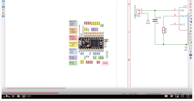
Adding pinout diagrams to schematics in KiCad
Chris Gammell shares many tips and tricks on Contextual Electronics including:
KiCad 5.0 – Adding pinout diagrams to schematics
It’s useful to have a reference item right next to the schematic you’re working on. This tip shows how to add that in and make sure it doesn’t print with the rest of your schematic.
A Network Attached VFD Tube Clock
The elegance of Power over Ethernet (PoE) is that you can provide network connectivity and power over a single cable. Unfortunately not nearly enough hardware seems to support this capability, forcing intrepid hackers to take matters into their own hands. The latest in this line of single-cable creations is this beautiful Vacuum Fluorescent Display (VFD) clock from [Glen Akins].
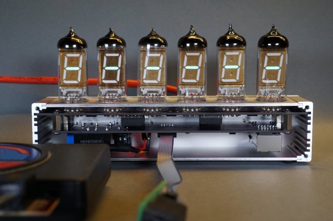
One of the key advantages VFDs have over their Nixie predecessors is greatly reduced energy consumption, and after [Glen] ran the numbers, he saw that a display using six VFD tubes could easily be powered with standard PoE hardware. With this information, he started designing the PCB around the early 1990s era IV-12 tube, which has the advantage of being socketed so he could easily remove them later if necessary.
[Glen] first had to create a schematic and PCB footprint for the IV-12 tube that he could import into Eagle, which he was kind enough to share should anyone else be working with these particular tubes down the line. After a test of the newly designed socket was successful, he moved onto the rest of the electronics.
The clock is powered by a Microchip PIC18F67J60, which connects to the Ethernet network and pulls the current time down from NTP. After seeing so many clocks use an ESP to connect to the Internet over WiFi, there’s something refreshing about seeing a wired version. The tube segments are driven by a HV5812, also Microchip branded. Lastly, [Glen] used a number of DC/DC converters to generate the 1.5 V, 3.3 V, 5 V, and 25 V necessary to drive all the electronics and VFDs.
We absolutely love the simplicity of this clock, from its sleek aluminum enclosure to that single RJ45 jack on the back. But if you’re looking for something with a bit more flash, [Glen] also put together some PoE Christmas lights over the holidays which share a number of design elements with this project.


