µGame by Radomir Dopieralski

Radomir Dopieralski has created handheld game console programmable with (Micro/Circuit)Python:
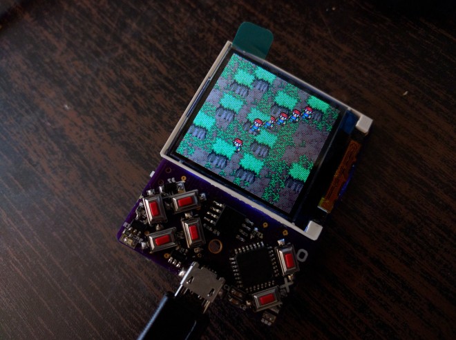
2179411509287391232.jpg

µGame

A small game console directly programmable in Python. I always wanted to make this, and after my work on #PewPew FeatherWing I finally decided that I’m ready.

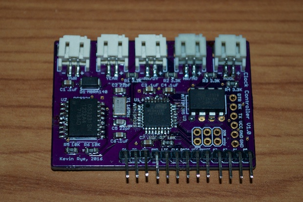
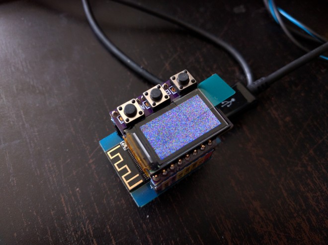
The first version may be a bit of a stretch — I tried to make it as small as possible, fitting in the 5x5cm limit of PCB manufacturers, so that it will be cheap to make the PCBs. Using the cheap ST7735 TFT display, and a cheap ATSAMD21E chip. I also tried to put all the components on one side of the board, but failed with that — the power and reset switch had to go on the back, as well as the buzzer.
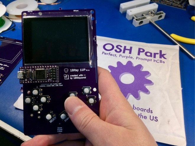
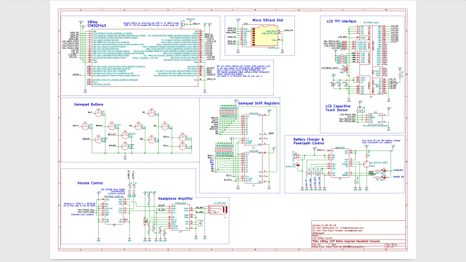


µGame by Radomir Dopieralski

Wemos D1 Mini Breakout for an ST7735 Display

Radomir Dopieralski has created this breakout board to make it easier to slap a popular ST7735 module on top of a Wemos D1 Mini:

8571081501668647022.jpg

D1 Mini Breakout for an ST7735 Display

There is a number of options you have for display shields for the D1 Mini: there is the nice OLED shield, there is a shield with a single WS1228B neopixel, there is the #D1 Mini Matrix Shield I’m still working on. But there is no high-resolution color display you could just slap on it. This “shield” doesn’t really deserve the name, it’s just a simple breakout board that connects the ST7735 display module with the SPI pins of the D1 Mini, and adds a trim pot for brightness control.

4514121484133413329.png

To save some pins, the CS pin is hardwired to GND, and the A0 pin is connected to MISO. That means you can’t connect other SPI devices while this is in, but that’s a rare enough case for me to care. It uses four GPIOs total, from GPIO12 to GPIO15. The backlight is connected to the 5V supply (to not strain the on-board 3V3 regulator) through a trim pot, so you can adjust brightness.

I used alternating holes for the module’s header, so that with some luck you should be able to plug in the module directly, without soldering a female pin header there — that should also save some space.

Wemos D1 Mini Breakout for an ST7735 Display

1Bitsy 1UP handheld game console

We’re excited about this new project from Piotr Esden-Tempski of 1BitSquared on Hackaday.io:
1641161499897782709.jpg

1Bitsy 1UP

1Bitsy 1UP is a retro inspired handheld game console, the design is based on the 1Bitsy STM32F415RGT6 ARM Cortex-M4F 168MHz 192kb RAM and 1MB Flash micro controller. 2.8″ TFT with capacitive touch, SDCard Reader and a few other components.

The display used is a TFT LCD with I2C CapTouch and ILI9341 driver. (should be compatible with the display sold by Adafruit on their breakouts as well as the buydisplay.com 2.8″ tft with CapTouch sensor)

Screenshot from 2017-07-13 21-08-58.png

The most basic design consists of:

  • 1Bitsy STM32F415RGT6 (168MHz, 192kb RAM, 1MB Flash)
  • 240×320 2.8″ TFT with capacitive touch and PWM backlight control
  • D-Pad, ABXY, Start, Select buttons
  • DAC audio out to headphones. (speakers optional)
  • SDCard connected over SDIO interface

The hardware design files and firmware source code are available on GitHub:

github1bitsy/1bitsy-1up

1Bitsy 1UP handheld game console

KiCad footprint for Nokia 5110 LCD

Sven Gregori on Hackaday.io created a KiCad component and footprint for the Nokia 5110 LCD and created this breakout board to test it:8695331498520943537

Yet another Nokia 5110 LCD breakout board

I just shamelessly measured all there was to measure and created my own KiCad PCB footprint, along with a schematic component.

Once done, I needed a way to verify it would actually work and fit the LCD, so despite how pointless it is, I created my own breakout board as proof of concept and ordered it from OSH Park.

2564051498753691661

The Nokia 5110/3310 LCD component and footprint are available on GitHub:

Screenshot from 2017-06-10 14-39-57

sgreg has shared the breakout board on OSH Park:

Nokia 5110 LCD Breakout Board Rev.A

19e63d03bf94e53b32eed69f1556c35b

Order from OSH Park

KiCad footprint for Nokia 5110 LCD

Chronio DIY Watch

 writes on Hackaday:

Chronio DIY Watch: Slick and Low Power

[Max K] has been testing the battery life of his self-designed watch under real-world conditions. Six months later, the nominally 3 V, 160 mAh CR2025 cell is reading 2.85 V, so the end is near, but that’s quite a feat for a home-engineered smart watch

Chronio DIY Watch

3 Inch Tall 7-segment Clock

lcd_clock_final_build11-1

Kevin Rye decided to build a 15 inch long digital clock after acquiring these 3 inch 7-segment displays.  He documented the project from start to finish:

s101d22tr_0001 (1).jpg

I picked up these sweet LUMEX S101D22TR 7-Segment LCDs the other day.

3inlcdclock_assembly_0142

The PCBs for the hours, minutes, and seconds display modules are identical. They’ll just be wired differently.

dsc_0146

On the driver boards, data flows in from the left out to the next section on the right.

LumexLCDClockworking_0147

The source files can be downloaded from:

15inch-LCD-Clock-Source.zip

Screenshot at 2016-10-26 23-34-48.png

3 Inch Tall 7-segment Clock