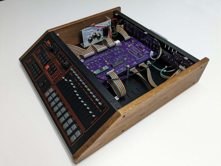
The Human League, Yazoo, Gary Numan, Giorgio Moroder, Devo, Prince…Roger Linn’s LM-1 drum machine helped create the signature sound of a huge number of artists in the 80s. After receiving an original LM-1 as a gift, Joe Britt (of Danger Research/T-Mobile Sidekick fame) decided to create his own enhanced version, based on the original TTL and Zilog Z80 design, but with a Teensy 4.1 coprocessor.
The original hardware design is enhanced with RAM-based samples instead of ROM, allowing the selection of different sounds. The original front panel switches are replaced with potentiometers that enable panning or pitch control. After countless hours of reverse engineering, Joe discovered that Roger Linn lived just five minutes away, and the two became fast friends as they geeked out on the neo-retro project together. The Luma-1 is a work in progress, with new features like an LCD screen, MIDI, and a new metal chassis appearing over time. Read more about on Roger Linn’s web site, and check out a demo in the video below!
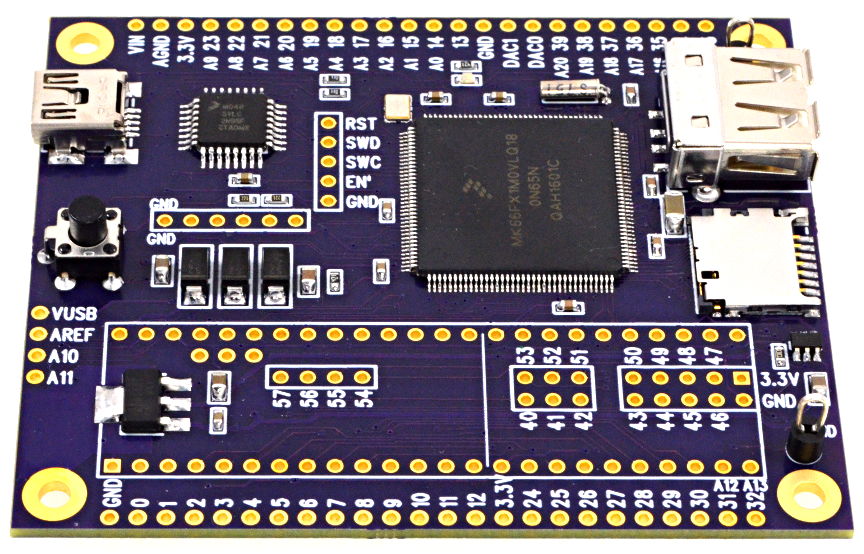
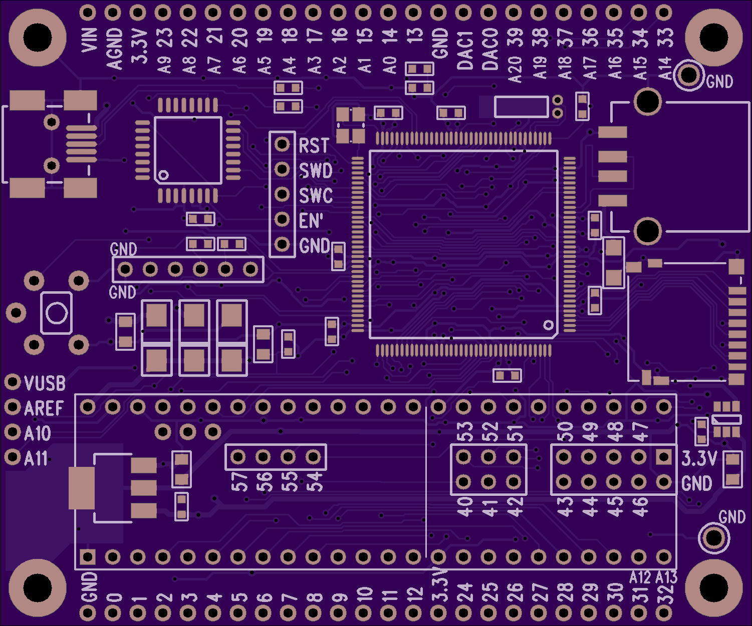
It was only last August that PJRC released Teensy 4.0. At that time, the 4.0 became the fastest microcontroller development board on the planet, a title it still holds as of this writing — or, well, not exactly. Today the Teensy 4.1 has been released, and using the same 600 MHz ARM Cortex M7 under the hood, is now also the fastest microcontroller board. What the 4.1 brings to the table is more peripherals, memory, and GPIOs. While Teensy 4.0 used the same small form factor as the 3.2, Teensy 4.1 uses the larger board size of the 3.5/3.6 to expose the extra goodies.
The now slightly older Teensy 4.0 — released on August 7th of last year — is priced at $19.95, with the new 4.1 version offered at $26.85. It seems that the 4.1 isn’t intended as a replacement for the 4.0, as they serve different segments of the market. If you’re looking for an ultra-fast affordable microcontroller board that lives up to its Teensy name, the 4.0 fits the bill. On the other hand, if you need the additional peripherals broken out and can afford the space of the larger board, the not-as-teensy-sized 4.1 is for you. How big is it? The sample board I measured was 61 x 18 mm (2.4 x 0. 7″), not counting the small protrusion of the micro-usb jack on one end.
Let’s have a look at all the fun stuff PJRC was able to pack into this space.
100 MBPS ETHERNET
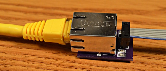
The big news is that Teensy 4.1 comes with 100 Mbps Ethernet support. To use the Ethernet port, you need to supply external magnetics and an RJ-45 jack. These were left off the board for obvious reasons — even using a jack with integrated magnetics (magjack), it wouldn’t fit on the PCB. Instead, a 6-pin header on the board can connect to an external interface. This also helps keep the price low for those who need the other features of the 4.1 without Ethernet connectivity.
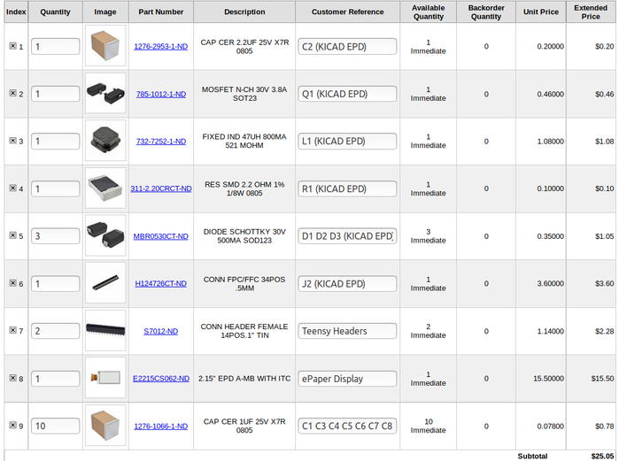
PJRC will likely sell a DIY kit of the required parts in the future, but they don’t have a release date or pricing yet. For now, you can easily build your own using this OSH Park shared project. The parts list is in the project’s description, with the key part being the magjack, which will set you back around $2.55 in single quantities. Those building a board should note that this is an early version, and it turns out that only the 0.1 uF capacitor is necessary. Paul Stoffregen of PJRC told me that he just received a simpler PCB for testing, and will publish the design once it’s has been thoroughly verified.
The Ethernet port is capable of full 100 Mbps speed and supports the IEEE 1588 precision time protocol, which allows synchronization of clocks to within 100 ns over wired connections, enabling some very interesting possibilities. But, aside from that, just the inclusion of Ethernet on a microcontroller board is a big deal. Before this, you basically had two choices if you needed this kind of connectivity: use a powerful single-board-computer like a Raspberry Pi with all the latency and headaches the required operating system brings for doing low-level or real-time tasks, or add a slow SPI-interfaced Ethernet board to an existing microcontroller. Instead, you can now use the 600 MHz Cortex-M7 on this new board to run high-bandwidth, low-latency embedded applications without fighting an OS.
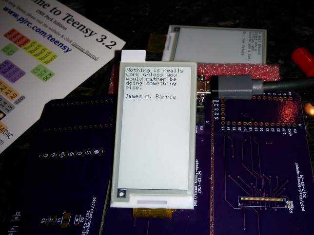
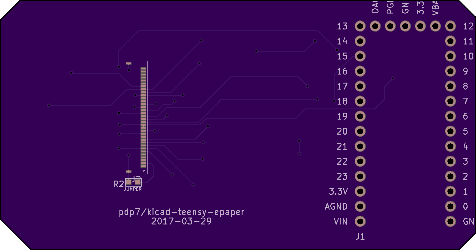
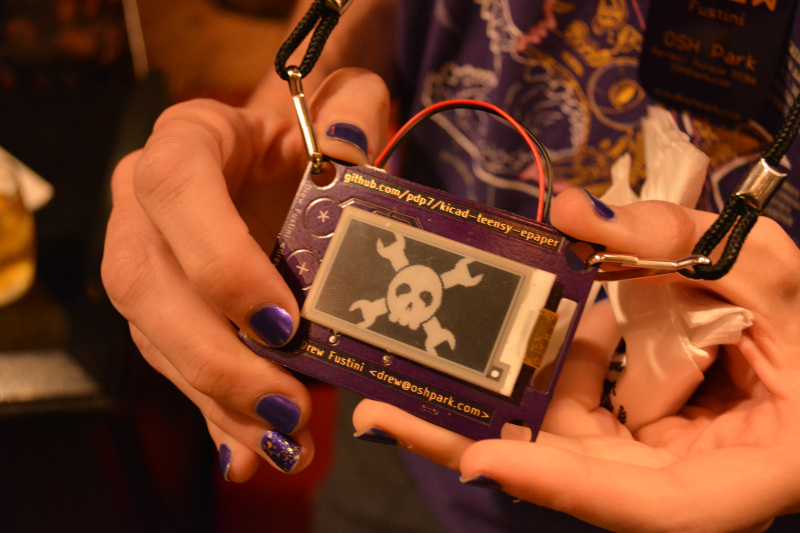
Friend of Hackaday, Drew Fustini, came to our Breakfast at DEF CON meetup sporting a name badge of his own design. The E-Paper Badge uses a Teensy LC to drive a 2.15″ E-Paper display. The row of capacitive touch buttons to the left allow the image to be changed, and he just happened to have the Jolly Wrencher in the gallery of choices for this picture.
This badge gets me really excited for this year’s Open Hardware Summit which is at MIT on September 27th. This year’s badge is a collaborative effort between a group on Hackaday.io! It’s basically Drew’s badge on steroids, and he told me the experience of working with a team has been really positive. It seems each time the group hits a hard problem or a pile of work that needs to be done, someone on the team grabs it and runs with it. It’s a great example of both certified open hardware and team development.
[Ross Fish], [Darcy Neal], [Ben Davis], and [Paul Stoffregen] created “the Monolith”, an interactive synth sculpture designed to showcase capabilities of the Teensy 3.6 microcontroller. The Monolith consists of a clear acrylic box covered in LED-lit arcade buttons. The forty buttons in front serve as an 8-step sequencer with five different voices, while touch sensors on the left…
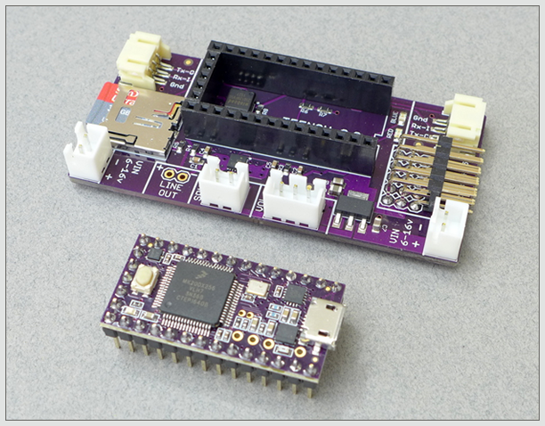
The Open Panzer Sound Card is a work in progress with the goal of bringing inexpensive, high quality, and open source sound functionality to RC models but especially to tanks using the Tank Control Board (TCB).
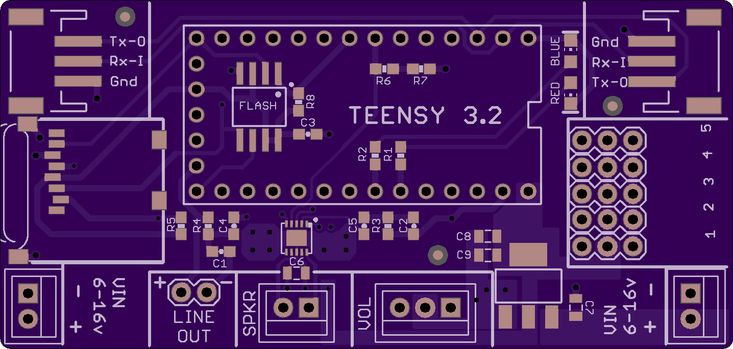
The board is actually made up of two components. First, an off-the-shelf PJRC Teensy 3.2 is used as the onboard processor. The Teensy is then plugged into a socket on our custom carrier board that adds a Micro SD card slot (max 32 GB), an additional 16 MB of flash memory, an LM48310 2.6 watt audio amplifier, and headers for external connections.
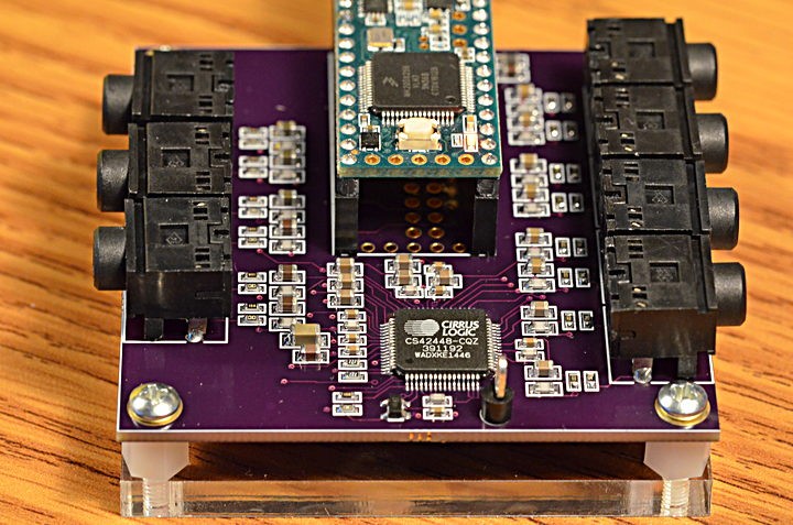
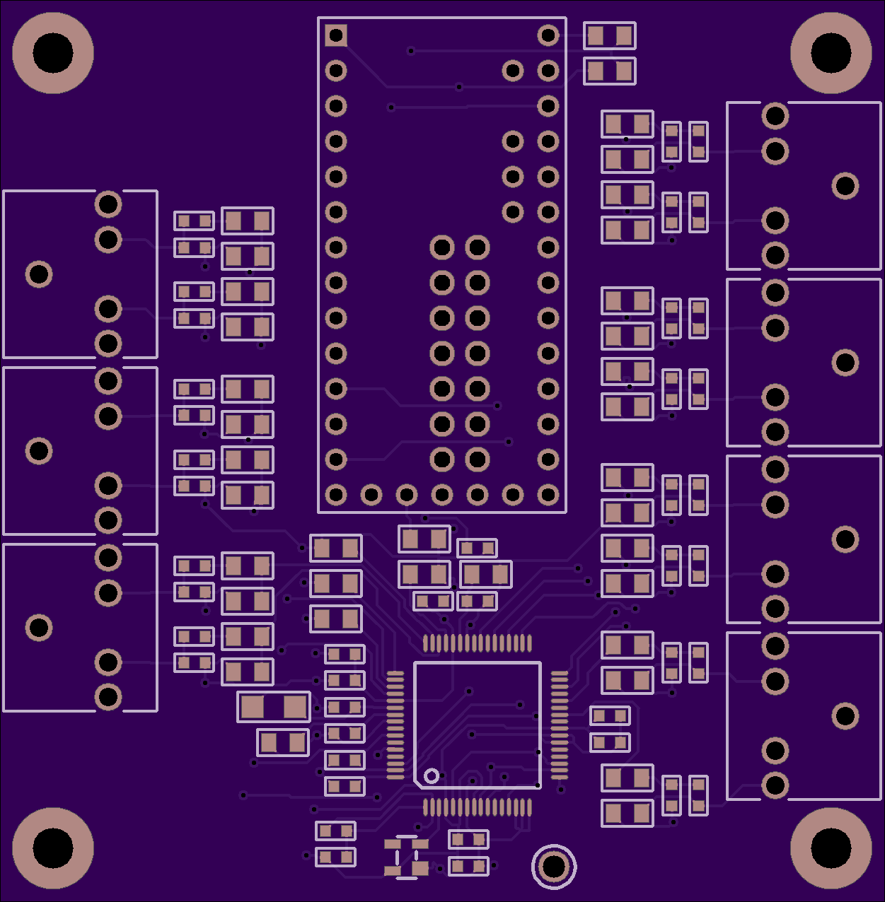
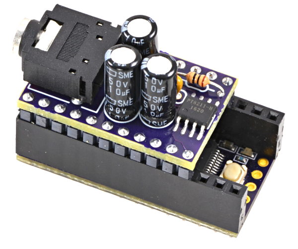
Some projects need a lot of audio I/O. Maybe you’re doing positional audio sound effects (using the 8-tap delay effect) where ordinary stereo or even 5 channel “surround” isn’t enough? Maybe you’re making the ultimate Eurorack synthesizer module? Or you just want a lot of signals, because you can!
Here’s a board for the Cirrus Logic CS42448 chip, which provides 6 inputs and 8 outputs. All are high quality audio, and all work simultaneously.
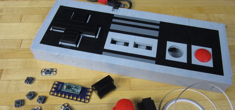
[BrownDogGadgets] built a giant NES controller out of LEGO. The controller is designed in LEGO Digital Designer, which lets you create a virtual model, then get a full list of parts which can be ordered online.
The electronics are based on a Teensy LC programmed to appear as a USB keyboard, and the buttons are standard push buttons. The insides are wired together with nylon conductive tape. LEGO was an appropriate choice because the Teensy and switches are built on top of LEGO compatible PCBs, so components are just snapped in place. The system is called Crazy Circuits and is a pretty neat way to turn electronics into a universal and reusable system.
Here is the controller in action:
Design files and source code for Crazy Circuits modules and projects are available on GitHub:
My goal is to create a name badge I can wear at conferences and Maker Faires. This was first step to verify the KiCad schematic and KiCad footprints work. I will post more information as the badge project progresses.


 BrownDogGadgets/CrazyCircuits