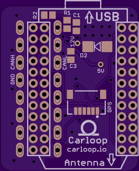
I wanted to make a compact internet-connected analyzer for my car’s OBD-II diagnostic port.
The WiFi-capable Particle Photon or better yet the cellular Particle Electron are great options for that.
Luckily the pins for a Photon fits right in between the 2 rows of pins of a straight OBD-II connector so it’s possible to make a very compact OBD-II adapter with a Photon.
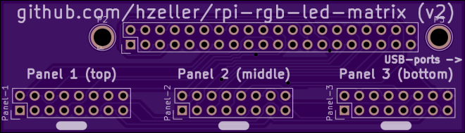
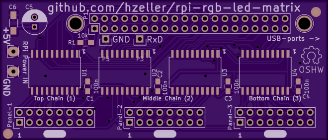
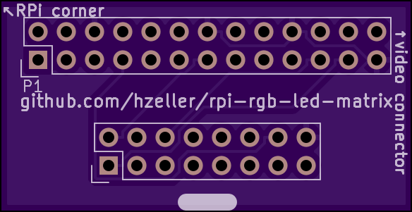
Controlling RGB LED display with Raspberry Pi GPIO
A library to control commonly available 32×32 or 16×32 RGB LED panels with the Raspberry Pi. Can support PWM up to 11Bit per channel, providing true 24bpp color with CIE1931 profile.
Supports 3 chains with many 32×32-panels each. On a Raspberry Pi 2, you can easily chain 12 panels in that chain (so 36 panels total), but you can stretch that to up to 96-ish panels (32 chain length) and still reach around 100Hz refresh rate with full 24Bit color (theoretical – never tested this; there might likely be timing problems with the panels that will creep up then). With fewer colors you can control even more, faster.
Here it is in action:
Henner has shared the his board designs on OSH Park:
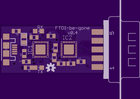
There are countless devices to add a traditional DB9M serial port via USB. The general problem is that when you just buy a cheap one, you don’t have any idea what’s inside. With the reminder of the recent FTDI shenanigans, it’s become more important to use modem “class” chips that use generic OS drivers rather than proprietary driver devices. Cypress Semi’s CY7C65213 is one such device. Because it uses drivers supplied by the OS, there’s no opportunity for them to attempt to weaponize a proprietary driver.
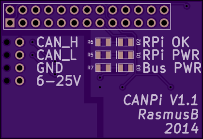
This is an electrically isolated CANBUS adapter for your Raspberry Pi. Even if you screw up the connections somehow, nothing will be damaged. It also fits within the normal Raspberry Pi footprint, meaning that you can use it with most enclosures.
The board was designed with KiCAD and the design files are on GitHub:
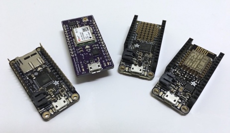
Dan Watson of the The Sync Channel Blog has been designing exciting FeatherWings (e.g. daughterboards) for the Adafruit Feather line of microcontroller development boards. Dan wrote a nice introduction to Feather:
“Occasionally I see a new product or microcontroller development board that really sparks my interest. That’s what happened with the Adafruit Feather line of boards. They pack a lot of punch into a small footprint, especially when you consider the fact that LiPo charging is built-in, as well as Wi-Fi, Bluetooth, or an SD card on some of the variants.”
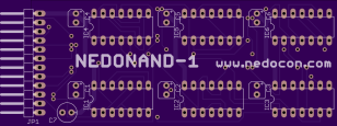
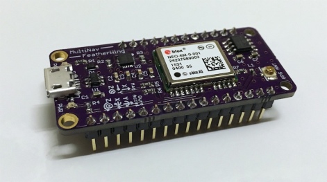
Dan designed a FeatherWing that combines a GPS and 9DOF IMU sensor:
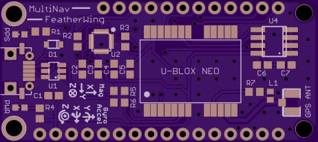
“The MultiNav FeatherWing is an add-on board for Adafruit Feather. It incorporates a U-Blox NEO-6M GPS module as well as an InvenSense MPU-9250 9 Degrees of Freedom (9DOF) sensor.”
He also added the board as as OSH Park Shared Project:
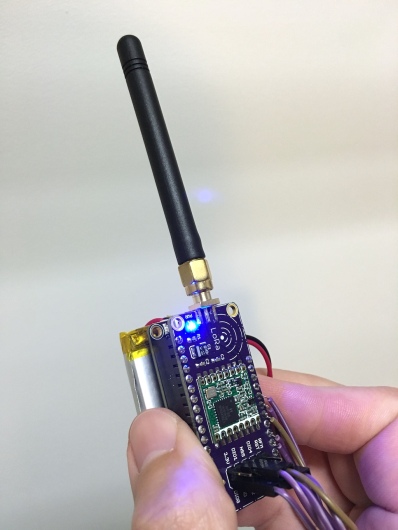
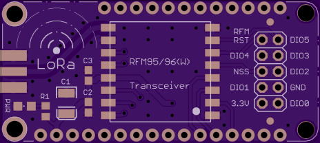
“LoRa is an ultra-long range wireless technology that uses sub-GHz ISM bands. It allows the interconnection of small, low-power sensor nodes and Internet of Things (IoT) devices. There are many LoRa transceiver modules on the market from manufacturers such as HopeRF and MicroChip.”
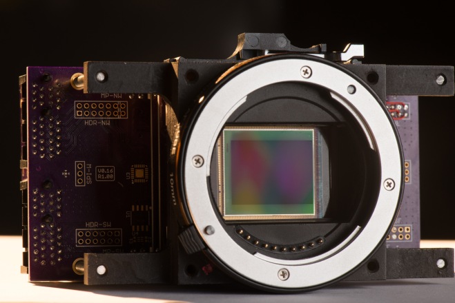
We are very excited about Apertus and their mission to create an Open Source Cinema Camera:
The goal of the award winning apertus° project is to create free and open technology for todays professional cinema and film production landscape and make all the generated knowledge freely available.
The apertus° project is based on software free to be used for any purpose, free to be studied, examined, modified and redistributed – which includes distributing your modified versions. Hence, products and services developed by apertus° are almost exclusively released under GNU General Public License V3 . * Documentation provided is licensed under the Creative Commons License and the hardware under the Cern Open Hardware License .
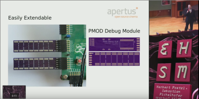
For example, their alpha-hardwarerepo contains Axiom Alpha prototype hardware source files (electronic schematics, documentation, PCB layouts, etc.) including this handy debug board designed with EAGLE:
PMOD-Debug-LedMatrix
A very small PCB sporting 64 LEDs that connect to most FPGA development boards (like the Zedboard) with a PMOD interface. This PCB provides an easy way to debug FPGA logic with just 8 digital lines and a 4-to-16 line decoder with minimal interface logic required in the FPGA side (PL).
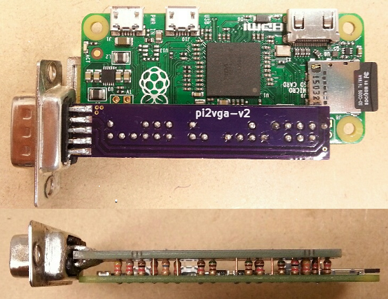
Hackday reports on this nifty hack for the Raspberry Pi Zero:
Hackaday.io user mincepi wanted a VGA output on his Raspberry Pi Zero. His quest led him to design a PCB that mates with a VGA monitor and the Pi board and–according to his estimates–costs about $3.62 each (although to get that price, you have to build three).
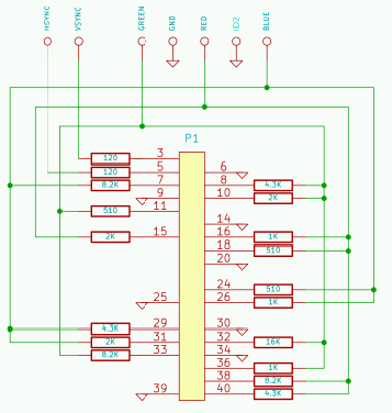
The vga666 by Gert is already a low cost VGA output option for the Pi. But we can do better with the Zero! First, we’ll use 16 bit output instead of 18 bit. This frees up the SPI and I2C ports with little loss in quality. The resistors can also be soldered between the Zero and the adapter, making the PCB smaller and eliminating a connector. I’ve also determined that 5% resistors are good enough: no need for higher cost 1% units. And by not using the middle row of pins in the HD15 connector, we can straddle-mount it on the PCB edge. The connector can be male, so the Zero will connect to the monitor ChromeCast style: no VGA cable needed. (This connector could even be scrounged from an old VGA monitor cable for free!)
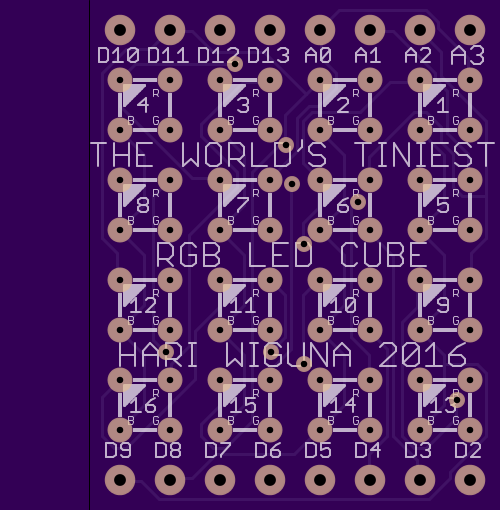
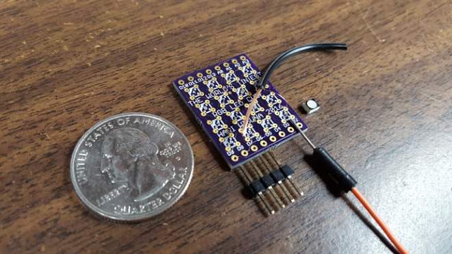
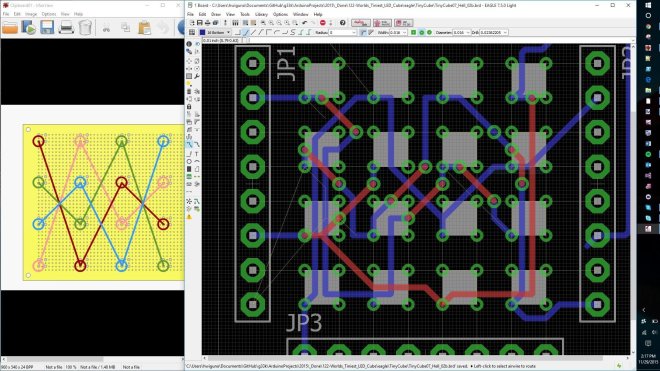
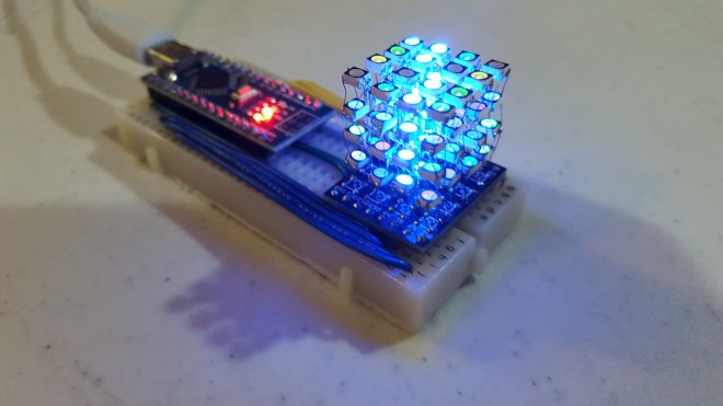
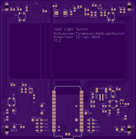
Hand soldered 4x4x4 RGB LED cube. Uses 2.7mm x 3.4mm SMD RGB LEDs. – The cube itself is less than 1″x1″x1″ on a slightly larger custom designed PCB. – 64 SMD (Surface Mounted Device) common anode RGB LEDs. – All driven by an Arduino Nano (WITHOUT any shift registers)