Are you bored of your traditional bow tie? Do you wish it had RGB LEDs, WiFi, and a web interface that you could access from your smartphone? If you’re like us at Hackaday…maybe not. But that hasn’t stopped [Stephen Hawes] from creating the Glowtie, an admittedly very slick piece of open source electronic neckwear that you can build yourself or even purchase as an assembled unit. Truly we’re living in the future.
Evolution of the Glowtie
While we’re hardly experts on fashion around these parts (please see the “About” page for evidence), we can absolutely appreciate the amount of time and effort [Stephen] has put into its design. Especially considering his decision to release the hardware and software as open source while still putting the device up on Kickstarter. We seen far too many Kickstarters promising to open the source up after they get the money, so we’re always glad to see a project that’s willing to put everything out there from the start.
For the hardware, [Stephen] has gone with the ever popular ESP8266 module and an array of WS2812B LEDs around the edge of the PCB. There’s also a tiny power switch on the bottom, and a USB port for charging the two 1S 300mAh lipo batteries on the backside of the Glowtie. The 3D printed rear panel gives the board some support, and features an integrated bracket that allows it to clip onto the top button of your shirt. For those that aren’t necessarily a fan of the bare PCB look or blinding people with exposed LEDs, there’s a cloth panel that covers the front of the Glowtie to not only diffuse the light but make it look a bit more like a real tie.
When you go to a hacker conference, you always hope there’s going to be a hardware badge. This is an interactive piece of custom electronics that gets you in the door while also delighting and entertaining during the con (and hopefully far beyond it).
Hot off the presses then is the Hacker Hotel badge, from the comfortable weekend hacker camp of that name in a Netherlands hotel. As we have already noted, this badge comes from the same team that created the SHA2017 hacker camp’s offering, and shares that badge’s display, ESP32 processor, battery, and firmware. The evolution of that firmware into the badge.team platform is an exciting development in its own right, but in the context of this badge it lends a very familiar feel to the interface for those attendees who were also at the 2017 event.
I used pcb-rnd to create a Printed Circuit Board (PCB) with a “geographical” shape, the shape of the state of Florida, for a Christmas present of six assembled devices for my brother who lives in Ocala Florida and is an avid geocacher. His geocache handle is marked on the board (obscured in video for his privacy) as is a space to write a tracking number. The LED at the “OCALA” logo will flash every 30 seconds. These electronic circuits are “trackables” that he will deposit in a geocache with the idea that it will be moved along. However, trackables are often kept by the finder as a souvenir.
The boards were made for me by OSHPark and hand assembled.
Elliot Williams and Mike Szczys look at all that’s happening in hackerdom. This week we dive deep into super-accurate clock chips, SPI and microcontroller trickery, a new (and cheap) part on the microcontroller block, touch-sensitive cloth, and taking a home X-ray to the third dimension.
Chris Gammell wants to know: What’s in your circuit toolbox?
Personally, mine is somewhat understocked. I do know that in one of my journals, probably from back in the 1980s, I scribbled down a schematic of a voltage multiplier I had just built, with the classic diode and capacitor ladder topology. I probably fed it from a small bell transformer, and I might have gotten a hundred volts or so out of it. I was so proud at the time that I wrote it down for posterity with the note, “I made this today!”
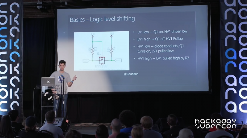
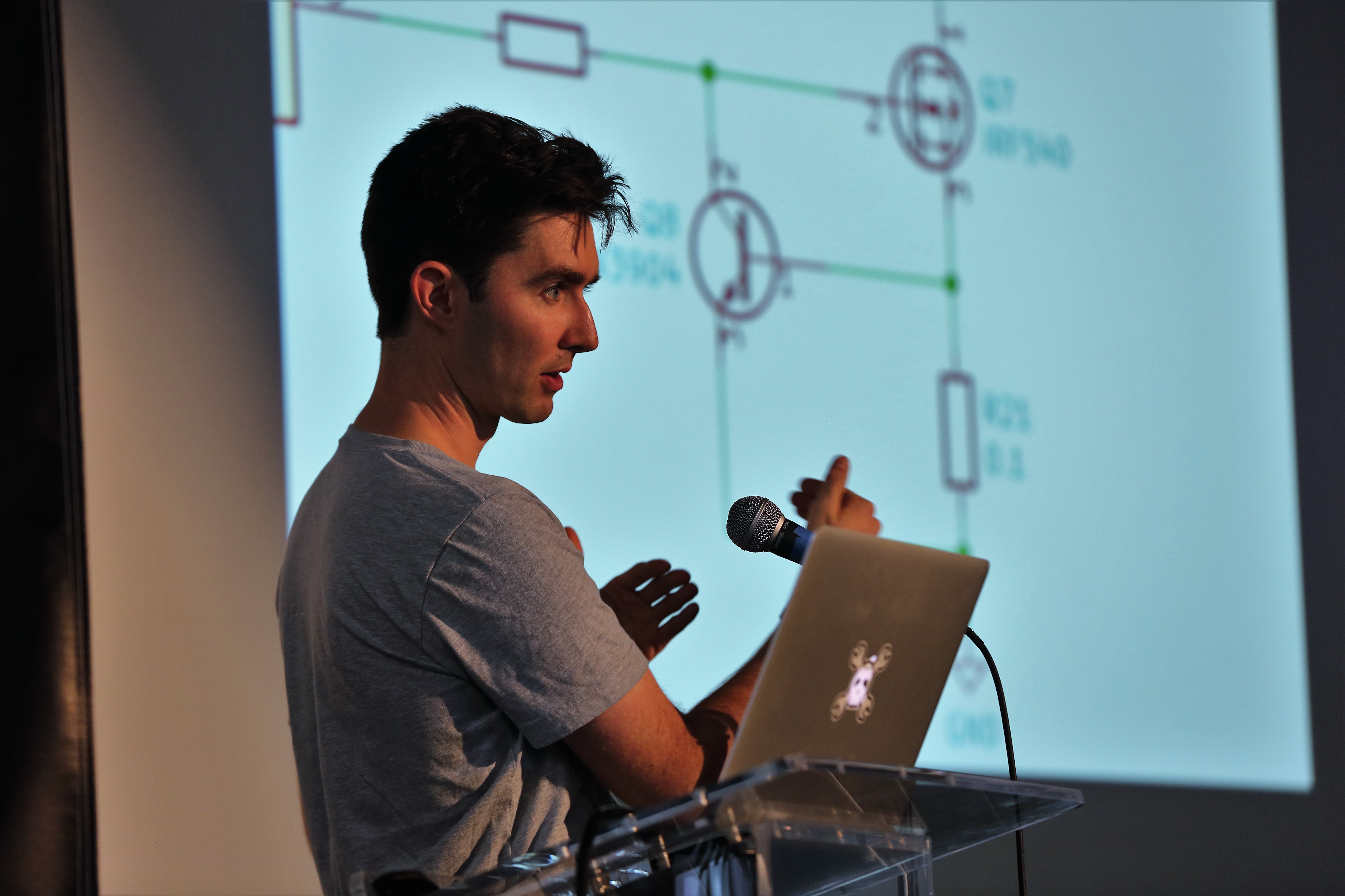
I think the whole point of Chris’ 2018 Hackaday Superconference talk is precisely what I was trying to get at when I made my “discovery” — we all have circuits that just work for us, and the more you have, the better. Most readers will recognize Chris from such venues as The Amp Hour, a weekly podcast he hosts with Dave Jones, and his KiCad tutorial videos. Chris has been in electrical engineering for nearly twenty years now, and he’s picked up a collection of go-to circuits that keep showing up in his designs and making life easier, which he graciously shared with the crowd.
As Chris points out, it’s the little circuits that can make the difference. Slide after slide of his talk had schematics with no more than a handful of components in them, covering applications from dead-simple LED power indicators and switch debouncing to IO expansion using a 74HC595. And as any sensible engineer might, Chris’ toolbox includes a good selection of power protection circuits, everything from polarity reversal protection with a MOSFET and a zener to a neat little high-side driver shutoff using a differential amp and an optoisolator.
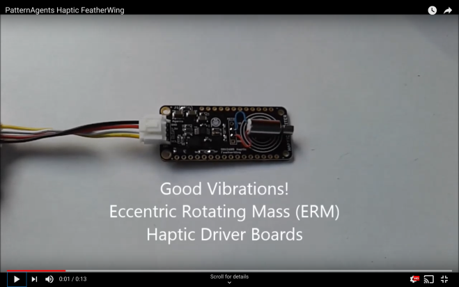
The Agent-DRV2605-FeatherWing allows you to connect Adafruit Feather CPUs,
and/or Grove System Modules all at the same time, using the Arduino Integrated Development Environment. This gives you maximum flexibility for sensor and actuator, selection and reuse.
TI DRV2605L Haptic Driver
ADI ADXL345 Accelerometer
FeatherWing I2C Compatible Module
Grove I2C Compatible Module
Integrated Current Measurement Connector
ERM Haptic Actuator support
LRA Haptic Actuator support
3.3V Operation
The Agent-DA7280-FeatherWing allows you to connect Adafruit Feather CPUs,
and/or Grove System Modules all at the same time, using the Arduino Integrated Development Environment. This gives you maximum flexibility for sensor and actuator, selection and reuse.
When writing code for the ATtiny family of microcontrollers such as a the ATtiny85 or ATtiny10, people usually use one of two methods: they either add support for the chip in the Arduino IDE, or they crack open their text editor of choice and do everything manually. 296 more words
When writing code for the ATtiny family of microcontrollers such as a the ATtiny85 or ATtiny10, people usually use one of two methods: they either add support for the chip in the Arduino IDE, or they crack open their text editor of choice and do everything manually. Plus of course there are the stragglers out there using Eclipse. But [Wayne Holder] thinks there’s a better way.
The project started out as a simple way for [Wayne] to program the ATtiny10 in C under Mac OS, but has since evolved into an open source, cross-platform integrated development environment (IDE) for programming a wide range of ATtiny chips in C, C++, or Assembly. Not only does it integrate the source code editor and programmer, but it even bundles in documentation for common variants of the chips including block diagrams and pinouts; making it a true one-stop-shop for ATtiny hacking.
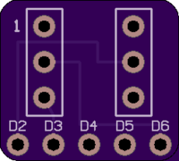
To actually get the code onto the chip, the IDE supports using the Arduino as a programmer as well as dedicated hardware like the BusPirate or the USBasp. If you go the Arduino route, [Wayne] has even come up with a little adapter board which he’s made available through OSH Park to help wrangle the diminutive chips.
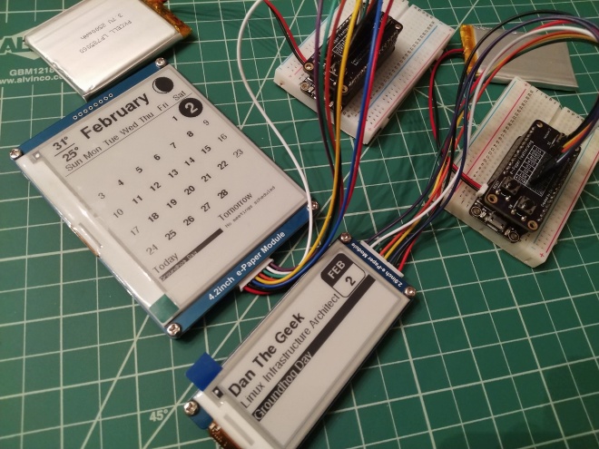
I wanted to create a few projects interfacing an e-paper display with the Adafruit HUZZAH 8266 and HUZZAH 32. The HUZZAH microcontrollers are a great fit with e-paper displays. In addition to having WiFi connectivity to grab date, weather and calendar information from the internet, they also can power themselves down and wake up at a later time. Since the e-paper displays retain their display without power, this makes for a great symbiotic relationship. Running the HUZZAHs with the e-paper display for just a few minutes each day can allow the device to run for weeks or even months depending on the size of the battery.
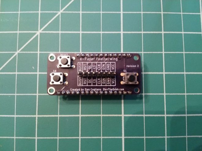
In all, I was very happy with the result. I no longer need to hand solder a dozen or so wires on a small proto board and the final product looks very clean. Having the same board compatible with both the HUZZAH 8266 and HUZZAH 32 is an extra bonus. I am putting the finishing touches on the code for a monthly calendar display and name plate/badge that you can see in the photo at the top of this article. This code will be released to GitHub and described in a future article.