Designing your own integrated circuits as a one-person operation from your home workshop sounds like science fiction. But 20 years ago, so did rolling your own circuit boards to host a 600 MHz microcontroller with firmware you wrote yourself. Turns out silicon design isn’t nearly as out of reach as it used to be and…
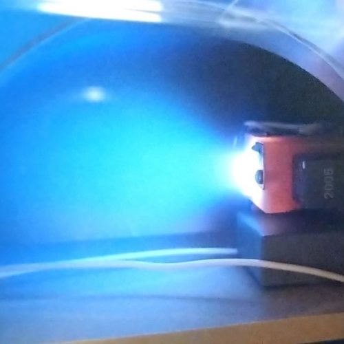
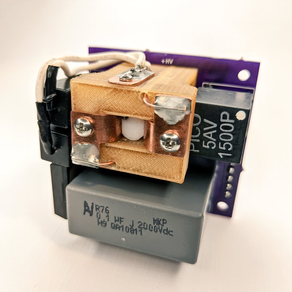
The AIS-EPPT1 Pulsed Plasma Thruster an experimental pulsed plasma thruster design aimed at low-cost, easy to manufacture, and simplified propulsion for Cubesats and PocketQubes. This system takes lessons learned from the original AIS-gPPT3-1C Integrated Propulsion Module and further expands its capabilities to attempt to increase fuel capacity, improve ignition, performance, and ultimately lower PPT cost and simplify manufacturing. The highly compact thruster is small enough for integration with PocketQubes, and can be implemented as a single thruster, cluster, or attitude control for Cubesats.
Applied Ion Systems Patreon is now officially LIVE! Are you a space enthusiast who would like to contribute directly to development of advanced EP from the only official open source electric propulsion program out there? Let's pioneer the field together! https://t.co/Nh9mqkSA4M
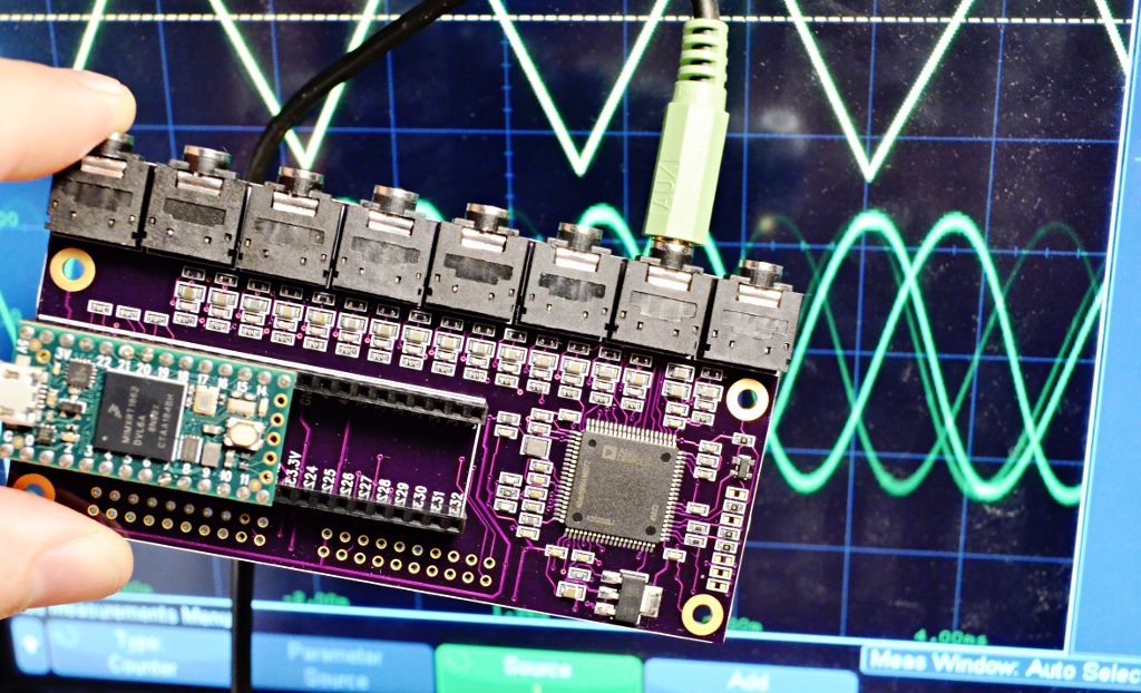
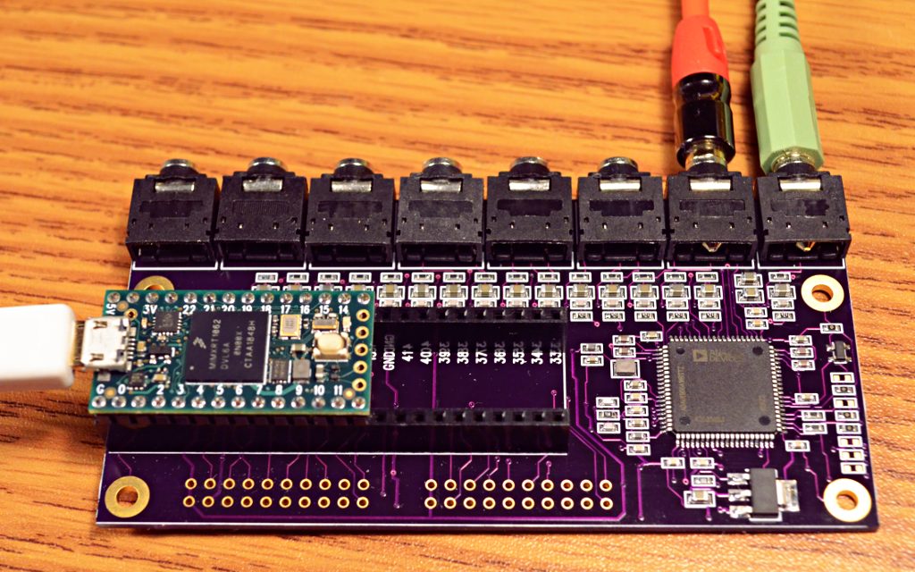
Today I dusted off a 16 channel DAC PCB I had designed on a whim back in March. Fiddled ’til I found settings to make the ADAU1966A spring to life. It’s generating 16 distinct waveforms!
So far this PCB has only been tested with the code below. It does produce 16 different waveforms output with the correct frequencies and waveform shapes. The board seems to work, but no other testing has yet been done (or perhaps by the time you’re reading this, maybe this page is old info….)
This board uses the ADAU1966A chip from Analog Devices. Analog Devices also made an older version of this chip, ADAU1966 without the “A”. It is listed as not recommended for new designs. If you search and find the old chip, don’t worry. Just make sure you’re searching for ADAU1966A with the “A”.
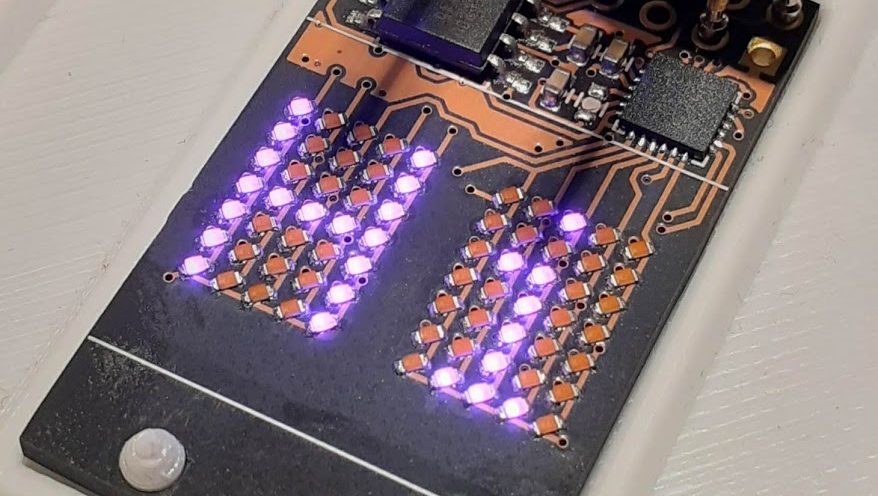
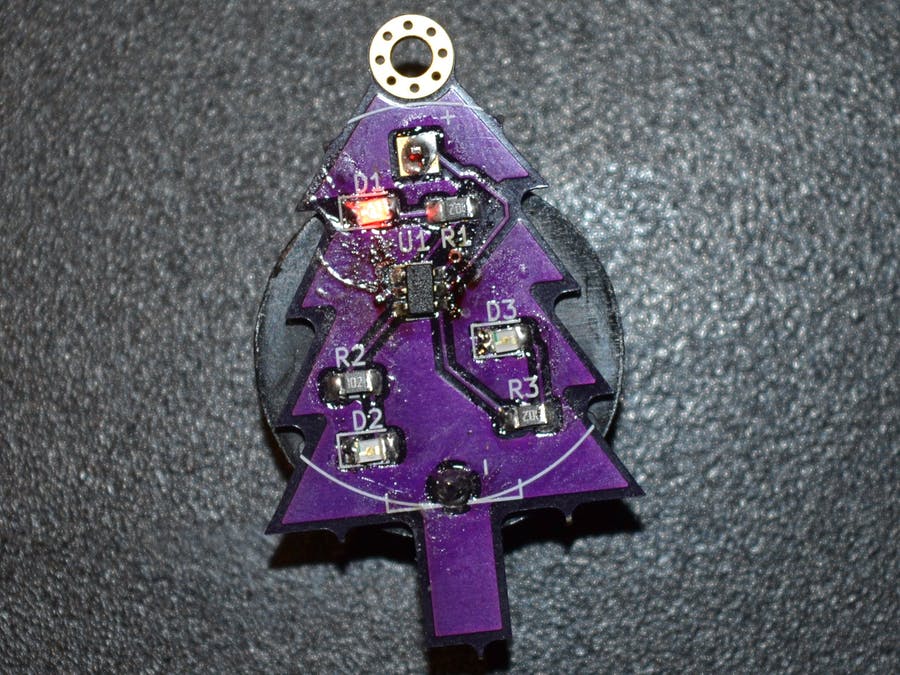
Few things excite a Hackaday staff member more than a glowing LED, so it should be no surprise that combining them together into a matrix really gets us going. Make that matrix tiny, addressable, and chainable and you know it’ll be a hit at the virtual water cooler. We’ve seen [tinyledmatrix]’s work before but he’s back with the COPXIE, a pair of tiny addressable displays on one PCBA.
The sample boards seen at top are a particularly eye catching combination of OSH Park After Dark PCB and mysterious purple SMT LEDs that really explain the entire premise. Each PCBA holds two groups of discrete LEDs each arranged into a 5×7 display. There’s enough density here for a full Latin character set and simple icons and graphics, so there should be enough flexibility for all the NTP-synced desk clocks and train timetables a temporally obsessed hacker could want.
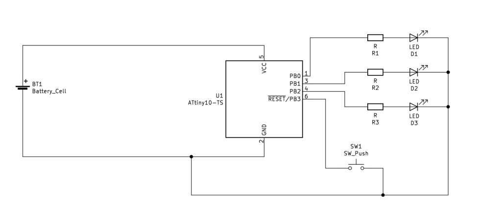
But a display is only as good as it’s SDK, right? The COPXIE is actually designed to be a drop in replacement for a different series of tiny LED matrices, the PIXIE by [Lixie Labs]. To complete the effect the COPXIE runs the same firmware and so has the same feature set. Each module (with two displays) can be controlled with just two pins (data and clock), and chains of more than 12 modules (24 displays) can be strung together. Plus there is a convenient Arduino friendly library which makes control a snap.
To build a COPXIE of your own, check out the schematic linked on the Hackaday.io page, and the layout at the OSH Park share link. Note that it seems like [tinyledmatrix] may not have completely validated these boards, but given there are plenty of photos of them working they seem like a safe bet.
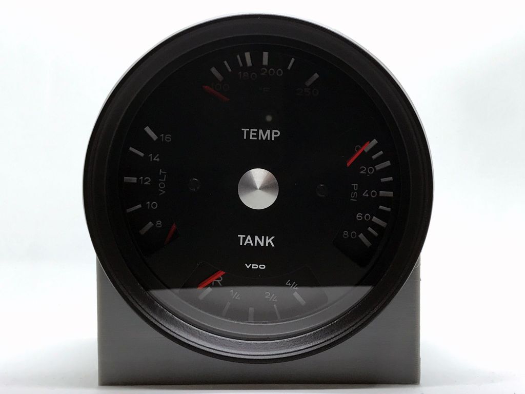
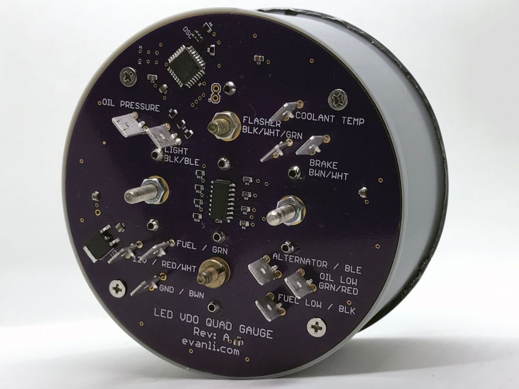
I’ve recently become the co-owner of a 1972 Porsche 914 with a 5.7L LS1 swap. As a result of the shift from air cooled to water cooled, the car required the addition of a gauge for coolant temperature. An oil pressure gauge was also added and the two gauges sat together, mounted on the floor near the shifter. It didn’t look great
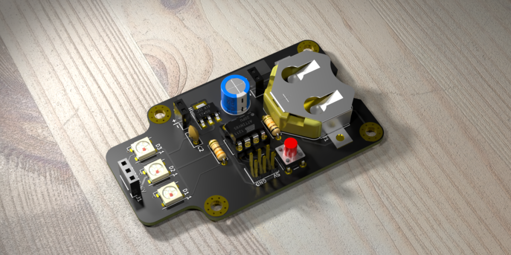
In this workshop, Anool Mahidharia takes the output of KiCad’s VRML export, gets it rendering in Blender, and then starts tweaking the result until you’re almost not sure if it’s the real thing or a 3D model. He starts off with a board in KiCad, included in the project’s GitHub repo, and you can follow along through the basic import, or go all the way to copying the graphics off the top of an ATtiny85 and making sure that the insides of the through-plated holes match the tops.
If you don’t know Blender, maybe you don’t know how comprehensive a 3D modelling and animation tool it is. And with the incredible power comes a notoriously steep learning curve up a high mountain. Anool doesn’t even try to turn you into a Blender expert, but focuses on the tweaks and tricks that you’ll need to make good looking PCB renders. You’ll find general purpose Blender tutorials everywhere on the net, but if you want something PCB-specific, you’ve come to the right place.
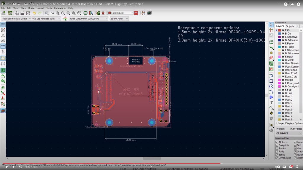
Raspberry Pi released the Compute Module 4 (CM4) in October, which is a single board computer with all of the processing power of the Raspberry Pi 4, but in a tiny form factor! It removes many of the connectors (USB, HDMI, etc.), as the intention is for you to add your own with a custom board and enclosure.
In this series, we’ll show you how to create your own, custom Raspberry Pi CM4 carrier board with KiCad!
With our new CP Sapling, there is a world of possibilities that you can explore with the SAMD21 microcontroller. And thanks to the hard work of Adafruit, there is a ton of great examples that can be used to explore microcontroller functionality and make a few cool projects to impress your family this holiday season!
As always before we get started, if you have never used a CircuitPython board like the QT PY, be sure to check out Adafruit’s learning site to quickly get started with your new board. –> Adafruit Learning Site: Getting Started With CircuitPython