The Dutch organisation eth0 has run a series of informal small camps over the years, never with an attendance too far into three figures, and without pre-planned events or entertainment. What happens is at the instigation of the attendees, and the result is a weekend of much closer socialising and working together on projects than the large camps where you spend your time running around to catch everything.
The largest of hacker camps offer all the lights, robots, tschunk, and techno music you can stomach; they can be a blast but also overwhelming. I made my way eth0 over the past week weekend, enjoying the more intimate size and coming away having made friendships from spending time with great people at a large private camping hostel near Lichtenvoorde. This is in the far east of the country near the German border, to which in the company of a British hardware hacker friend I traveled in the tiny European hatchback. Netherlands roads are so easy to navigate!
The badge itself has an interesting layout, because aside from a bit of badge.team and event related artwork it uses a multipurpose layout from Electronic Eel, that’s designed for both SMD and through-hole parts. This proved to be extremely versatile, but came with the slight burden that the through-hole pads were closely surrounded by the ground plane, making soldering a bit tricky. Despite this there was an enthusiastic take-up from camp attendees, with offerings that went well beyond the mundane.
For the majority of the attendees there was a badge bar, with plentiful supplies of LEDs ad other components. Some attendees made do with a pair of colour changing LEDs and a CR2032, but others made CMOS astable oscillators using 4093 Schmitt AND gates for the full flashing effect. It’s almost unexpected today when so much is done by microcontrollers to see people hacking logic gate oscillators, but there was a circuit bending element to it all that made for a more enjoyable experience.
A fully functional event badge built upon an event badge. Fuchsia’s Tamafoxi runs the badge.team firmware.
One or two badges sported extra lighting in the form of Neopixels and similar. This staple of the LED badge is the obvious choice for one like the eth0 badge, even with its relative lack of space. The piece de resistance of the eth0 winter 2019 badges though did not feature any LED lights, instead it came with a small OLED display and a set of buttons. Fuchsia’e Tamafoxi is a fully functional tamagotchi clone that runs under the badge.team badge firmware, for which a Wemos ESP32 board had been fitted to the back of the badge. Power wasn’t quite so elegant, requiring a small protoboard and LiPo cell sandwiched to the back of the badge, but for the feat of getting a badge that wouldn’t disgrace a much larger event running on what was in effect a fancy protoboard, we’ll forgive all that. Plenty of event badge teams have set out to achieve this level of functionality and not quite made it, so to do so on an event badge like this one is a very significant feat indeed.
This was a short camp by the standards of some others, starting on a Friday evening and wrapping up at Sunday lunchtime. We left in the drizzle of a damp autumn afternoon for the easy trip to the overnight ferry across the billiard-table-smooth Dutch motorways, without some of the stress of limited access while packing that comes with the larger camps. It had been everything we’d wanted from a small hacker camp and more, so speaking personally I’d certainly head back to this one if the opportunity arose.
We are big fans Hackaday Supercon and several of the OSH Park team will be attending again this year from November 15 – 17. Here’s some of what to look forward to:
Four weeks from today the Hackaday Superconference comes alive for the fifth year. From engineering in challenging environments to elevating the art form of electronics, here are nine more talks that will make this a year to remember.
In addition to the slate of speakers below there are three other announcements, plus workshops. Jeroen Domburg (aka Sprite_TM) is designing this year’s badge based around a beefy FPGA running a RISC-V core and using open source synthesis tools. We’ll have more on that soon, but if you just can’t wait, check out the expansion board spec he just published, and join the conference chat room for the inside track. Badge hacking is sure to be the liveliest we’ve ever seen.
Tickets are sold out but you can still get on the waiting list and hope that one becomes available. If you are holding onto one of these hot commodities but are unable to use it, please return your ticket so that we can get it to someone waiting with their fingers crossed.
Rarely during product development do you get it correct on the first design iteration. Something always goes wrong or just isn’t perfect. However, like trying for a hole-in-one on a par 3, you always try for perfection but expect to need a few extra strokes. So, while I almost hit a hole in one in the first version of the Nixie Tube HAT (Part 1), a few improvements were required. In this blog, I describe the few improvements found from Part 1 and complete the design to reach stage 6 of the surfncircuits defined development flow. As with the other projects in the blog, the complete design files in Kicad, schematics, layout, BOM, are available at GitHub for use in your own projects. You can build it yourself and the PCB can also be ordered directly from Oshpark.
We love seeing the astonishing array of projects large and small entered into Hackaday contests which push the boundaries of what is possible. Our latest has been the Connected World contest which was announced back in June, and today we’re pleased to bring you its four top winners.
We love watching the creativity unleashed by the democratization of once-exotic technologies. The casualness by which one can order a cheap, small run of PCBs has unlocked a flood of fine pitch components and projects which look commercial quality even with a total build volume of one. Now the once mythical flex PCB has been falling from it’s stratospheric pricing and with OSHPark’s offering it feels like we’re at the inflection point. [qwertymodo] leveraged this by creating a beautifully twisted flex to add link port support to the Super Game Boy
In the mid-90’s Nintendo released the Super Game Boy, a cartridge for the SNES which allowed you to play Game Boy games on the big screen. Each cartridge was in fact an entire Game Boy with the appropriate hardware to present it in a way the host console could interface with, but missing some of the hardware a standalone Game Boy would include like a link port to connect it to another system. This mod fixes this limitation by bridging the correct pins out from the CPU to a breakout board which includes the link port connector. For general background on what’s going on here, check out [Brian]’s article from Aprildescribing a different mod [qwertymodo] executed to the same system.
What’s fascinating is how elegant the mod is. Using a a flex here to create a completely custom, strangely shaped, one-of-a-kind adapter for this random IC, in low volume is an awesome example of the use of advanced manufacturing techniques to take our hacks to the next level.
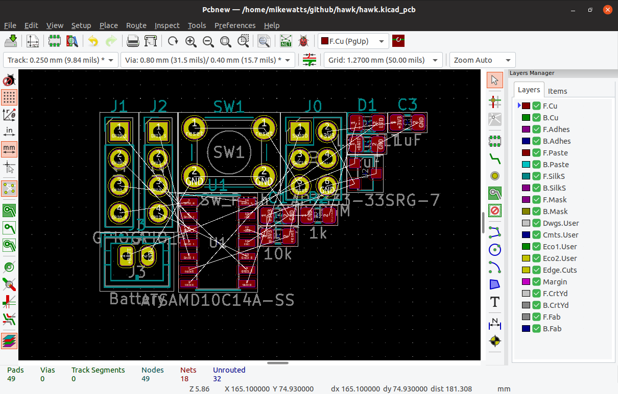
KiCAD has a rightfully earned image problem regarding beginners. The shiny new version 5 has improved things (and we’re very excited for v6!) but the tool is a bit obtuse even when coming from a electronics design background, so we’re always excited to see new learning material. [Mike Watts] is the latest to join the esteemed group of people willing to export their knowledge with his KiCAD tutorial series on GitHub that takes the aspiring user from schematic through fab and assembly.
The tutorial is focused around the process of creating a development board for the dimuitive Microchip née Atmel ATSAMD10 Cortex M0 ARM CPU. It opens by asking the reader to create a schematic and proceeds to teach by directing them to perform certain actions then explaining what’s going on and which shortcuts can accelerate things. This method continues through layout, manufacturing, and assembly.
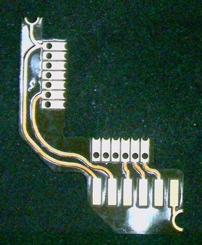
Of note is that when defining the board outline [Mike] describes how to use OpenSCAD to parametrically define it; a neat micro-tutorial on using the two great tools to compliment each other. We also love that upon successful completion of the tutorial series the user will have developed a tiny but useful development board that can be assembled for about $3 in single quantities!
As with all open source work, if you have quibbles or want to contribute open a pull request and give [Mike] a hand!
Digital Equipment Corp.’s PDP-11 is one of the most important computers in history. It’s the home of Unix, although that’s arguable, and it’s still being used in every application, from handling nuclear control rods to selling Ed Sheeran tickets on Ticketmaster. As the timeline of PDP-11 machines progressed, the hardware did as well, and by the time the PDP was eclipsed by the VAXxen, there were PDP-11s on a single chip. The Eastern Bloc took notice and produced their own PDP-11 on a chip. This is the 1801-series CPU, and like most soviet electronics from the Cold War, they’re readily available on eBay.
This project is the outgrowth of [SHAOS]’ project for last year’s Hackaday Prize, the PDPii. This was a computer built around a backplane that replicated the PDP-11 using a KR1801VM2 CPU, the Soviet not-a-clone clone of the PDP-11. This project is basically a PDP-11/03 system, except it was made in this century, and you can put it in any computer case, with bonus points awarded for RGB lighting and liquid cooling.
This year’s project, the PDPjr, eschews standardization to something that is far more unique. This build is more or less a single board computer with a character LCD display and a real keyboard. Think of this as the PDP-11 equivalent of the TRS-80 Model 100, a machine widely regarded as being the first laptop.
There’s still a lot of work to go, but [SHAOS] has written a ‘Hello World’ for this chip, and is getting those words to display on the character LCD. That’s a great first step and we can’t wait to see where this project ends up.
As hackers approached the dramatic stone entrance of Portland’s Pacific Northwest College of Arts, a group of acolytes belonging to The Church of Robotron beckoned them over, inviting them to attempt to earn the title of Mutant Saviour. The church uses hazardous environments, religious indoctrination, a 1980s arcade game and some seriously funny low tech hacks to test your abilities to save humanity. This offbeat welcome was a pretty good way to set the tone for Teardown 2019: an annual Crowd Supply event for engineers and artists who love hardware. Teardown is halfway between a conference and a party, with plenty of weird adventures to be had over the course of the weekend. Praise the Mutant! Embrace Futility! Rejoice in Error!
For those of us who failed to become the Mutant Saviour, there were plenty of consolation prizes. Kate Temkin and Mikaela Szekely’s talk on accessible USB tools was spectacular, and I loved following Sophi Kravitz’s journey as she made a remote-controlled blimp. Upstairs in the demo room, we had great fun playing with a pneumatic donut sprinkle pick and place machine from tinkrmind and Russell Senior’s hacked IBM daisywheel typewriter that prints ASCII art and runs a text-based Star Trek adventure game.
It wouldn’t be much of a hardware party if the end of the talks, demos and workshops meant the end of each day’s activities, but the Teardown team organised dinner and an afterparty in a different locations every night: Portland’s hackerspace ^H PDX, the swishy AutoDesk offices, and the vintage arcade game bar Ground Kontrol. There also was a raucous and hotly-contested scavenger hunt across the city, with codes to crack, locks to pick and bartenders to sweet talk into giving you the next clue (tip: tip).
Join me below for my favorite highlights of this three day (and night) festival.
When designing a printed circuit board, there are certain rules. You should place decoupling capacitors near the power pins to each chip. Your ground planes should be one gigantic fill of copper; two ground planes connected by a single trace is better known as an antenna. Analog sections should be kept separate from digital sections, and if you’re dealing with high voltage, that section needs to be isolated.
One that I hear a lot is that you must never put a 90-degree angle on a trace. Some fear the mere sight of a 90-degree angle on a PCB tells everyone you don’t know what you’re doing. But is there is really no greater sin than a 90-degree trace on a circuit board?
This conventional wisdom of eschewing 90-degree traces is baked into everything we know about circuit board design. It is the first thing you’re taught, and it’s the first thing you’ll criticize when you find a board with 90-degree traces. Do square traces actually matter? The short answer is no, but there’s still a reason we don’t do it.
We’re on the lookout for the most interesting connected projects, things that communicate wirelessly to do something clever. Show us your creations and you can win!


 In the mid-90’s Nintendo released the Super Game Boy, a cartridge for the SNES which allowed you to play Game Boy games on the big screen. Each cartridge was in fact an entire Game Boy with the appropriate hardware to present it in a way the host console could interface with, but missing some of the hardware a standalone Game Boy would include like a link port to connect it to another system. This mod fixes this limitation by bridging the correct pins out from the CPU to a breakout board which includes the link port connector. For general background on what’s going on here, check out