Finishing the IN-9/IN-13 Nixie Tube Driver for the Raspberry Pi (Part 2)

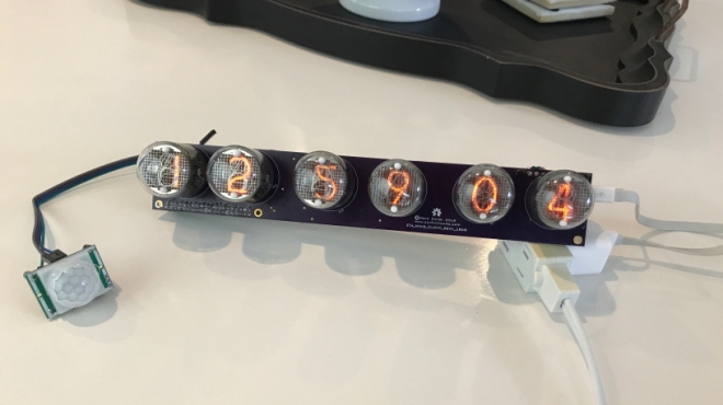
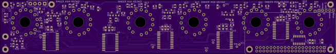
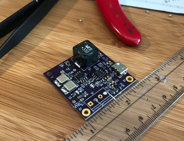
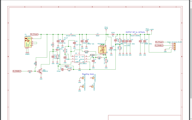
Mark Smith writes on the Surf ‘n Circuits blog about a Nixie Tube project:

Finishing the IN-9/IN-13 Nixie Tube Driver for the Raspberry Pi (Part 2)

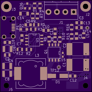
Rarely during product development do you get it correct on the first design iteration. Something always goes wrong or just isn’t perfect. However, like trying for a hole-in-one on a par 3, you always try for perfection but expect to need a few extra strokes. So, while I almost hit a hole in one in the first version of the Nixie Tube HAT (Part 1), a few improvements were required. In this blog, I describe the few improvements found from Part 1 and complete the design to reach stage 6 of the surfncircuits defined development flow. As with the other projects in the blog, the complete design files in Kicad, schematics, layout, BOM, are available at GitHub for use in your own projects. You can build it yourself and the PCB can also be ordered directly from Oshpark.

Quote

Estimated Time of Arrival (ETA) Nixie Tube Clock

From Mark Smith on the Surf ‘n Circuits blog:

4f9e07f8-8527-4256-bd58-c69a521f223c-4140-0000071679b34fd1_file-e1522612873965

What is an ETA Nixie Tube Clock and How Do You Build One?

Adding IOT to the Nixie Tube Clock. A clock that provides the estimated time of arrival for up to ten destinations

The ETA Nixie clock is programmed to display the normal time and up to ten different ETA times that are easy to identify and visually stimulating. The current time is displayed for 5 seconds (i.e. 8:41:38 AM), then up to ten different ETA destinations are displayed for three seconds each before the cycle is repeated. The current time displays all six digits including seconds. The ETA locations are numbered and display hours and minutes without seconds helping to distinguish between them.  In our house, the ETA to work is ETA number 1 (i.e. 9:07 AM) and the ETA to school is ETA number 2 (i.e. 8:58 AM). Lots of other options are possible with custom programming of the Raspberry Pi to meet your ETA requirements.

surfncircuits has shared the board on OSH Park:

An Estimated Time of Arrival (ETA) Nixie Tube Clock Rev 2.

ff5a9c545d1c50e39dc57941c7e174bf.png

Order from OSH Park

Estimated Time of Arrival (ETA) Nixie Tube Clock

Nicely Engineered Boost Converter Powers Nixies from USB Charger

Love them or hate them, Nixies are here to stay. Their enduring appeal is due in no small part to the fact that they’re hardly plug-and-play; generating the high-voltage needed to drive the retro displays is part of their charm. But most Nixie power supplies seem to want 9 volts or more on the input side, which can make integrating them into the typical USB-powered microcontroller project difficult.

Fixing that problem is the idea behind [Mark Smith]’s 5-volt Nixie power supply. The overall goal is simple: 5 volts in, 170 volts out at 20 mA. But [Mark] paid special care to minimize the EMI output of the boost converter through careful design, and he managed to pack everything into a compact 14-cm² PCB. He subjected his initial design to a lot of careful experimentation to verify that he had met his design goals, and then embarked on a little tweaking mission in KiCad to trim the PCB’s footprint down by 27%. The three separate blog posts are well worth a read by anyone interested in learning about electronics design.

Now that [Mark] has his Nixie power supply, what will become of it? We can’t say for sure, but it’ll be a clock. It’s always a clock. Unless it’s a power meter or a speedometer.

via Nicely Engineered Boost Converter Powers Nixies from USB Charger — Hackaday

Nicely Engineered Boost Converter Powers Nixies from USB Charger

Optimizing the 5v to 170v Nixie Tube Power Supply Design

From Mark Smith on the Surf ‘n Circuits blog:

img_5710-e1517644972331

Optimizing the 5v to 170v Nixie Tube Power Supply Design

A few years ago, while managing the power management product line at work, I started an initiative with the development team to optimize new products by achieving ESE.  ESE stands for Equations = Simulations = Experimentation.   The idea is centered on the engineering goal of product design to verify that the systems design equations match the simulation results and ultimately the experimental results.

When these three items match, not only do you understand a system, but you have the best chance to optimize a better solution.  I’ll have to say that in today’s mad dash to get new products out the door, achieving ESE is not always possible.    But to break through the ordinary and have a chance for the extraordinary, I would say this is a requirement.    Since this power supply is just a fun design for an upcoming nixie tube clock project of mine, I have the time to achieve ESE.

The updated schematic, BOM, Kicad Layout, and design files are located at Github:

Screenshot from 2018-02-20 12-51-12

surfncircuits has shared the board on OSH Park:

NixieSupply5vto160vDCMBoost_Rev2_1804

a33e35e34768a5ee94a5a2c05456fffd
Order from OSH Park

Here is a quick video showing six IN-4 Nixie tubes being powered by a 5v iPhone charger:

Optimizing the 5v to 170v Nixie Tube Power Supply Design