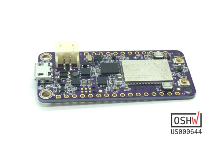
The nRF9160 Feather by Jared Wolff (aka Circuit Dojo LLC) is an electronics development board. It features tghe nRF9160 by Nordic Semiconductor. This part is capable of both CAT M1 LTE and NB-IoT for communication with the outside world. It’s compatible with the Zephyr RTOS which is fully baked into Nordic’s nRF Connect SDK. Other toolchains and languages coming soon to a Github repository near you.
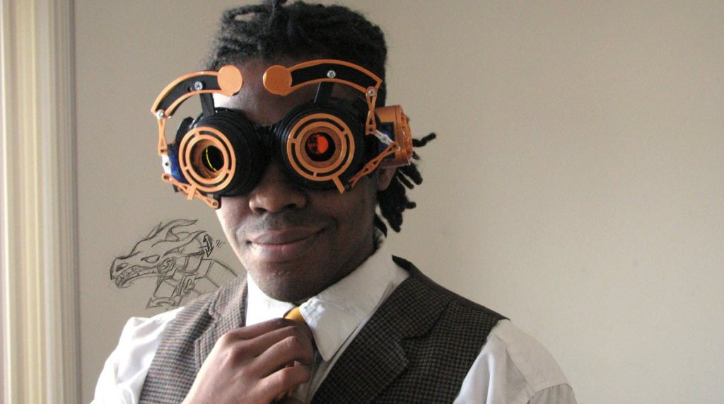
Jorvon Moss, known on Twitter as @Odd_Jayy, recently showed off his second pair of Magpie goggles with the tweet: “And this is why people called me odd growing up.” I reached out to him and he explained that the glasses were “a fun gadget that he put together really quickly over a weekend.” He programmed the 3D-printed mechanical device to open and close the irises and raise and lower separate eyebrows, using an Adafruit Trinket and two servo motors. More mechanical than digital, the goggles become part of a costume, and Jorvon becomes his own character. “Every sci-fi movie always had a really cool person with goggles,” Moss told me.
A video of him wearing the Magpie goggles “became a lot more popular than I thought,” he said. His Twitter followers, many of them makers he has gotten to know, cheered him on.
Moss began building robots about five years ago when he was in college. Like a lot of makers, he started doing it before he understood what he was doing, like artists who start drawing, even though they haven’t had a lot of training.
“Dexter is my personal favorite. And the thing about Dexter is that I’m always improving him. I’m always upgrading him. In a lot of ways, he’s growing up and a lot of people see him as my child.” Dexter is on V6, with over 160 components. He wants Dexter to become a wearable robot without the need of a backpack to carry various components. “I am designing a way for that to no longer be an issue,” he says.
The Earth Day Challenge is now under way! Spin up your take on an Earth-Day-themed electronics project and you’ll be in the running for one of the three $200 shopping sprees at Digi-Key, who are sponsoring this contest.
This is all about raising awareness for environmental projection. You might considered something as direct as measuring and plotting air quality data, or as abstract as weighing your home’s recycling bin and garbage bin and making a game out of generating less waste in general, and boosting your recycling-to-landfill ratio. Find an application that can be moved from grid-power to solar power, or build a carbon-savings counter that calculates the impact you have when choosing your bike over a car. The coolest projects are the ones that make us all think in new ways.
In addition to those $200 prizes for the top three projects, there are $50 Tindie gift cards for the twelve most artistically presented projects. Digi-Key is looking for great images to include in a wall calendar for 2022.
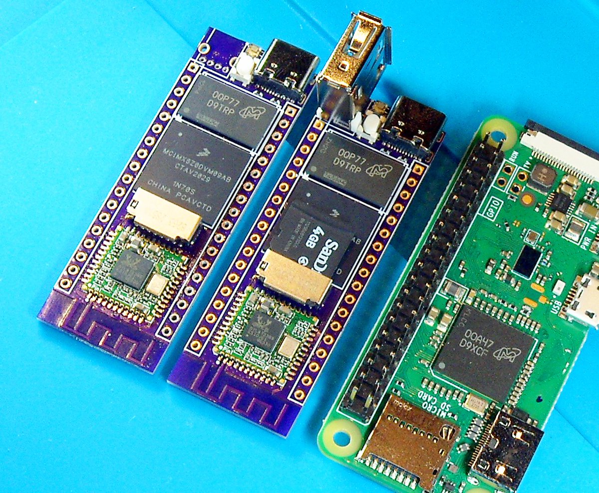
We recently did a test panel in anticipation of launching a 6 layer service. Jay Carlson took the opportunity to design a tiny breadboard-friendly board called the mxiot:
So what exactly was that 6-layer @oshpark PCB I was showing off earlier? It’s a small breadboard-friendly embedded Linux board I’m planning on open-sourcing once the design is verified. Here it’s pictured next to a Pi Zero, just to give you an idea of how tiny it is.
This board uses the $2.68 http://i.MX 6ULZ, a 900 MHz Cortex-A7. This part is specifically designed for smart-speaker-type applications and lacks the LCD/CSI/Ethernet controller found on the other http://i.MX 6ULL parts.
I’ve always wanted to do a small-form-factor embedded Linux breakout board, but it felt silly laying down a beefy part without ethernet or any of those big parallel multimedia interfaces available. The ULZ has none of that, so it’s a guilt-free form factor for the part.
This one supports standard 40-pin SDIO WiFi/BT modules, so you’ll have options for 802.11n or ac, and BT 4.0-5.0. I’m cheap, so I’ve mounted the RTL8723BS on these two.
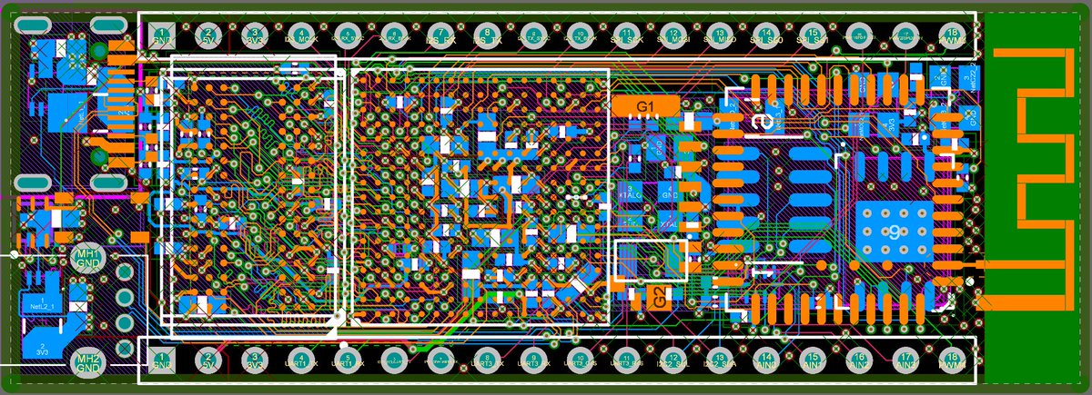
The biggest reason you’d have to go from 4L to 6L for designs like this is when you have to cram parts together. You don’t need HDI interconnects (since these are still huge-ass 0.8mm-pitch BGAs), but you definitely need internal routing layers.
The other reason to go to 6 layers is just ease of routing — this design only took a few hours to throw together. Most of the day was spent fretting in the pinmux tool over which pins to bring out to the headers and what should actually be on the board.
OK, so why would you want this instead of a Pi Zero, ARM9, or Cortex-A5 board? This one has a Cortex-A7 on it, so won’t run into as many compatibility issues with Node.JS, .NET Core, or other software packages useful for IoT projects.
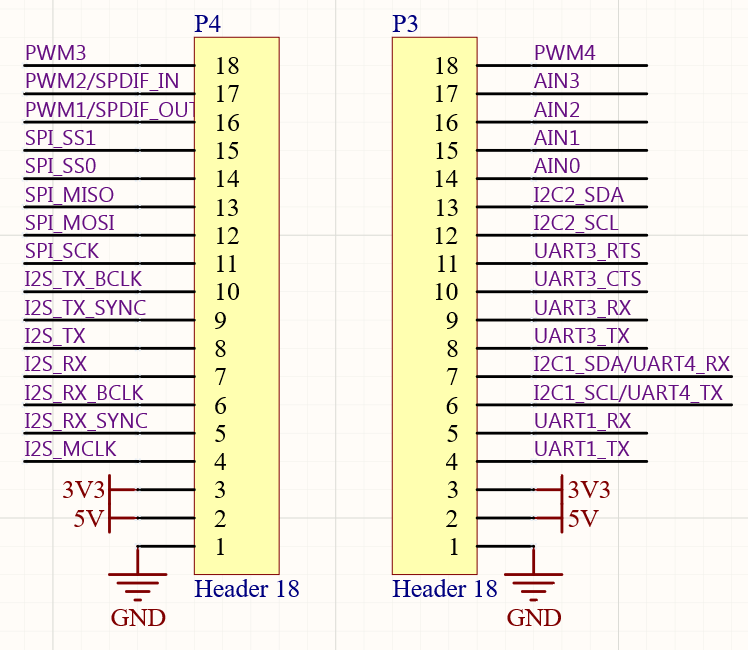
In addition to the onboard WiFi/BT, RGB LED, button, and USB connectors, the board has an I2S interface (with separate signals for RX and TX paths, plus SPDIF), 4 PWM channels, 4 12-bit ADC inputs, SPI, I2C, a console UART, a full UART (good for LTE modems), and a spare UART/I2C.
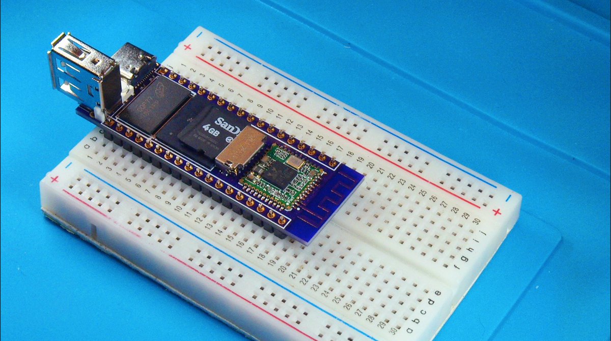
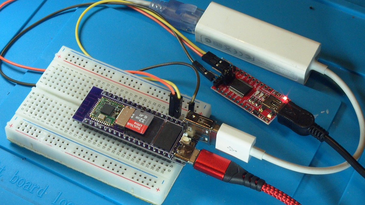
Just did a quick fit on a breadboard to make sure I didn’t have any clearance issues with the thru-hole USB connector. This thing is tiny! And yes, you get two free rows of breadboard pins on either side.
Parts for the bottom side didn’t arrive until today. My 0402 placement is drunk af, but a little heat and these guys pop right into place.
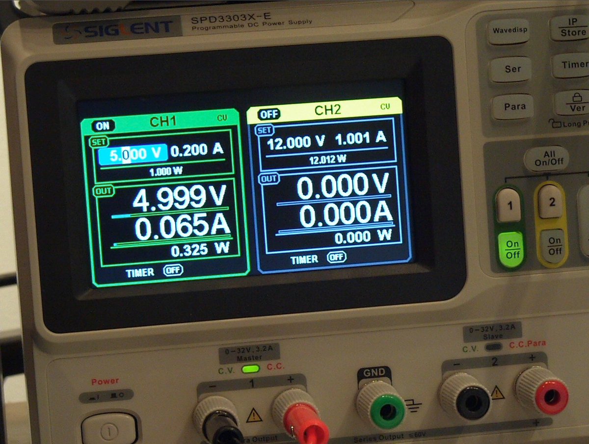
OK, onto bring-up: these buck converters don’t kick on until 2.7V, so you won’t see any current usage before that. Once current was flowing, I measured my 1.35V rail to make sure it wasn’t getting 100% duty-cycled to the input, which can happen if the FB pin isn’t connected
Exposing my 1.35V rail to 2.6V wouldn’t be great, but it’s a lot better than definitely frying it with 5V. Alright, the only other rail, 3.3V, can be verified the same way. Once that’s done, ramp it up to 5V and sanity-check the current consumption across all the assembled boards
(by the way, ramping up your supplies really slowly can put chips in weird states, so make sure to give it some fresh power to ensure your power sequencing is working)
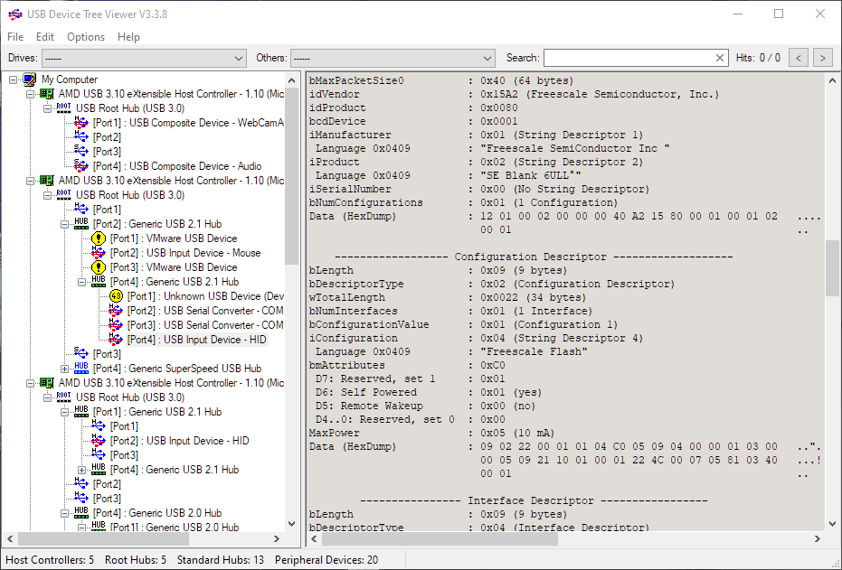
Like many application processors, the iMX6ULZ has a boot ROM that will instantiate as a USB device if attached to a computer. This HID device popped right up when I connected it to my computer, so I know core regulators work, the POR circuitry works, and USB pins aren’t shorted.
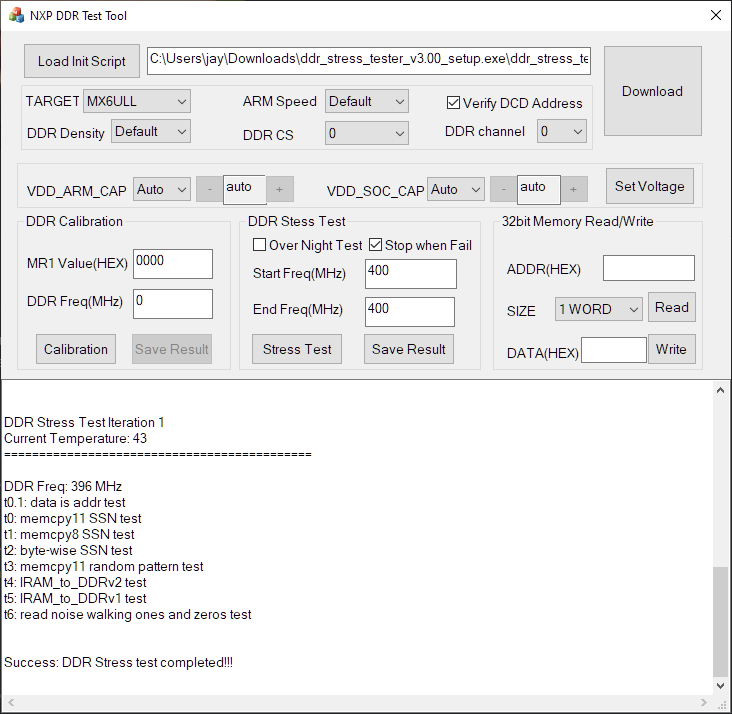
Usually, I’d get U-Boot working at this point, but I was recently reminded that NXP has a Windows GUI app that will stress-test your board over USB. Since PCB CAD is heavily Windows-based, it’s nice that hardware folks can test their board without needing to fire up a Linux VM.
Aaaaaaand it boots! Kind of. I need to get a U-Boot port and device tree going for the board, and there appears to be a weird MMC driver bug in U-Boot right now, so I had to steal a binary from a friend (thanks @EvanHailey!) to get things going. But it’s alive!
OK, I’ve verified enough of this design to feel comfortable pushing it out the door. Here it is!
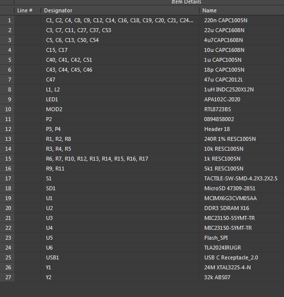
Since people appear to actually be looking at this, I cleaned up the BOM a bit and added it to the docs. Down to 27 lines, but if you use 10uF caps on all the 0603 pads you’d be down to 25. You could probably get away with 5k1 resistors on all 1-10k spots. down to 23. Not bad!
With the 3.3V regulator so close, the 47uF on the MicroSD could become a 10uF. Down to 22 lines. Don’t need an RTC? Then nix Y2. Now at 21 lines. Of course, the board would boot fine without the LED or pushbutton, and I haven’t even mounted the QSPI flash yet. BOM: 18 lines.
The whole “premature optimization” warning that everyone parrots to each other is so tired. I’m a big fan of aggressive BOM optimization early on if there’s a remote chance I’ll be hand-assembling any prototypes. BOM lines kill productivity at every step of the prototype process.
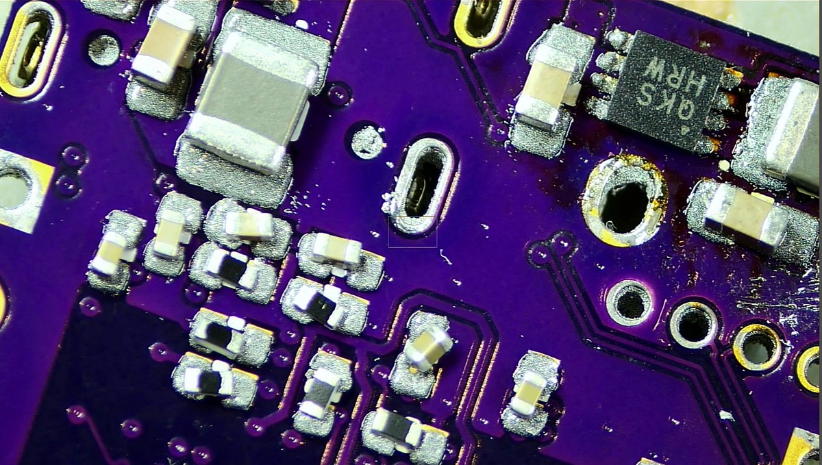
Got the boards in from @oshpark and got them put together! I’m pretty happy with how well they work. Its crazy that the silk is so sharp when each letter is less than 1mm across!
Thanks @BenSommerf for taking some sweet macro shots of these!
Pretty impressed at how well hot glue picks up the super tiny chip markings.
The renders of the project were pretty amazing too:
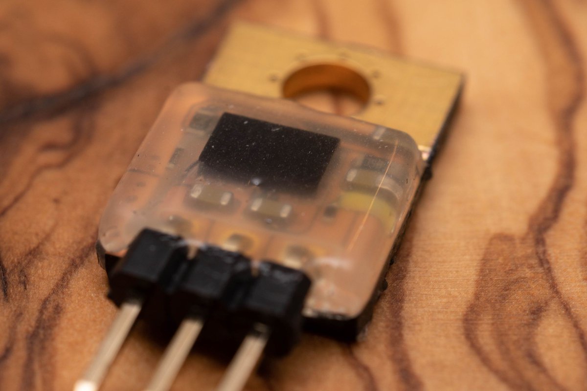
Decided to try out one of these integrated DC-DC converters. The small size means I can make it a drop in replacement for a TO-220 LDO. The @oshpark order is in! pic.twitter.com/Z4d8qgyHkd
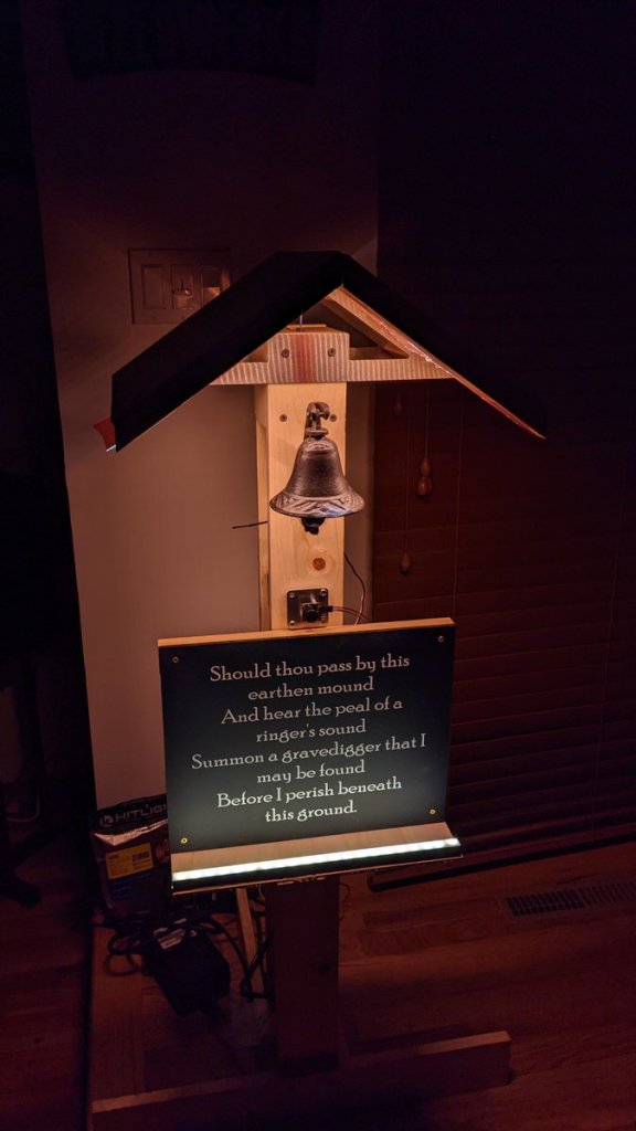
Glen Akins is already getting ready for Halloween!
Halloween grave bell triggered by ultrasonic range finder. Still need to cut side panels, build a small angled roof to make snow proof, add a power connector, mount electronics board inside, and clean up wiring.
Sick of seeing this icon during his MAME sessions, [Majenko] decided to attack the problem directly by taking a close look at the power supply circuitry of the Pi 4. While the official schematics for everyone’s favorite single-board computer are unfortunately incomplete, he was still able to identify a few components that struck him as a bit odd. While we wouldn’t necessarily recommend you rush out and make these same modifications to your own board, the early results are certainly promising.
The Open Hardware Summit (OHS) invites talk proposals for the eleventh annual summit! This year’s summit is virtual and will be held online on Friday 2021-04-09, 9:00 AM – 5:30 PM EDT.
Submissions are due by Thursday 2021-02-18 at 11 PM EDT.
Back in the 1970s, there were a huge variety of esoteric LED displays on the market. One of those was the DIP-packaged TIL311 from Texas Instruments, capable of displaying hexadecimal, from 0-9 and A-F. While these aren’t readily available anymore, the deep red plastic packages had some beauty to them, so [Alex] set about making a modern recreation.
The build consists of a small PCB fitted with 20 LEDs, and a STM8S microcontroller to run the show. This can be used to emulate the original decoder logic on the TIL311, or programmed with other firmware in order to test the display or enable other display functions. Where the project really shines however is in the visual presentation. [Alex] has been experimenting with potting the hardware in translucent red resin to properly emulate the look of the original parts, which goes a long way to getting that cool 70s aesthetic. Attention to detail is top notch, with [Alex] going so far as to carefully select pins that most closely match the square-cut design on the original TIL311 part.
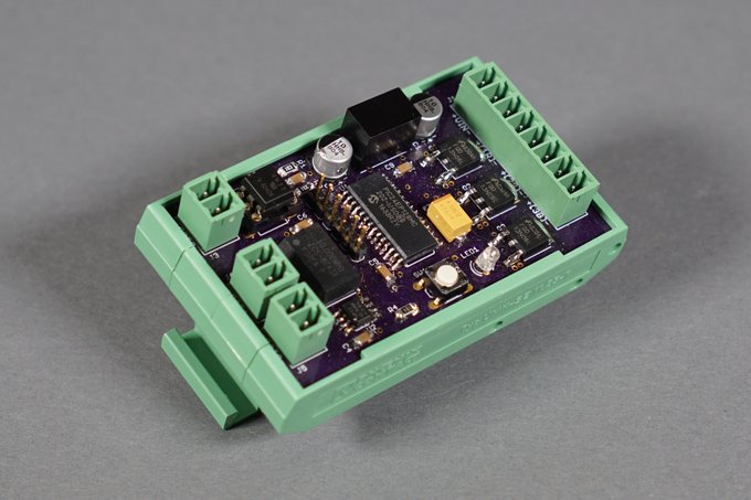
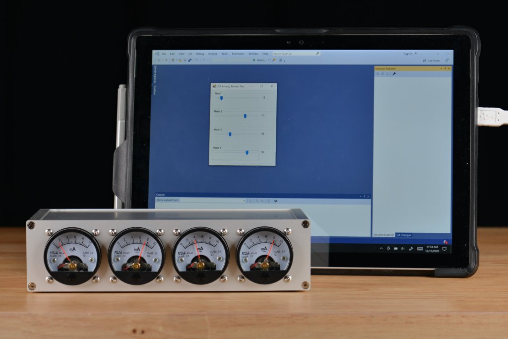
In the first part of this project, I acquired four round HUA SO-45 10 mA analog panel meters and built a board to control them over USB as a vendor-defined USB HID device. The next steps in this project are to build an enclosure for the meters and to develop a C# .NET graphical user interface to control them. Let’s take a look at designing the enclosure then we’ll take a look at building a simple Windows GUI to control them.
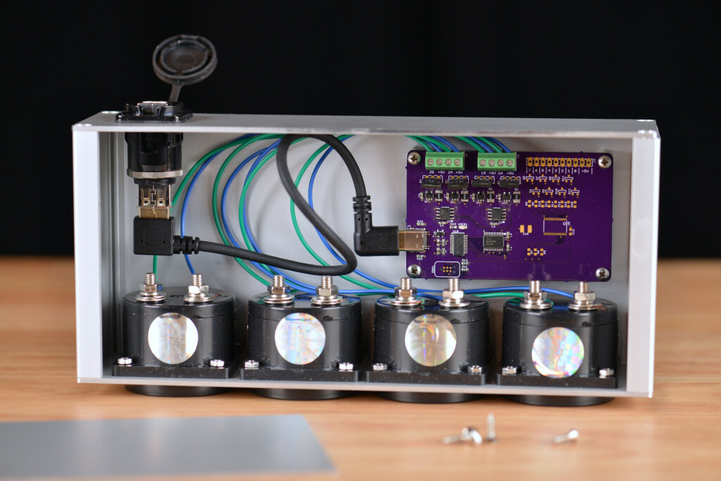
The inside of the enclosure is shown in the photo above. I used a short USB A to USB C right angle cable to connect the rear panel connector to the circuit board. There’s probably room for the three feet of cable on the USB C version of the rear panel connector but this seems to be the cleaner solution in my opinion.