Smart Home Power Line Communications Demo Board

JARViE created this dev board to create power line communications projects and products:

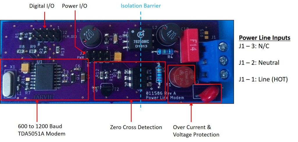
The JARViE PLM Demo Board offers users a simple and low-cost entry point into learning about Smart Home technology. Couple this modem with a microcontroller to bidirectionally communicate with other devices or systems over AC or DC power lines. Applications include lighting control, home appliance control, energy/heating control and up to 3,000 feet data transmission home power networks.

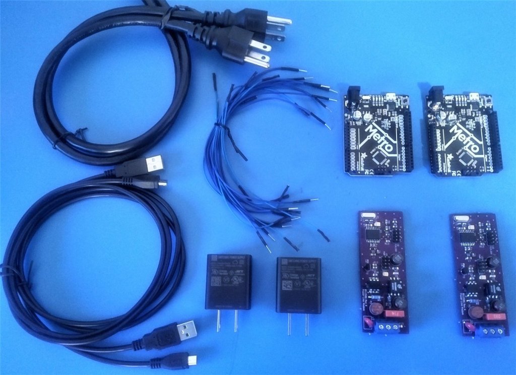
Each Demo board has an NXP TDA5051a powerline modem IC. This modem takes in a digital message from an MCUs UART bus, like an Arduino UNO, and translates this digital message into an equivalent analog message. Additional circuitry on the demo board sends the analog message over the 120/240VAC of your home, if the demo board is connected to a home outlet. Ideally, the analog message will be broadcasted across all the 120/240VAC wires of your home (to all home outlets), so another demo board connected to another home outlet will hear this message. The demo board has special filtering to only receive messages sent by other powerline modem demo boards and reject all other noise or communications between non-demo board devices. Once a demo board receives an analog message sent over the home power lines, it converts it to an equivalent digital message and sends it to an MCU over its UART bus. Additionally, the demo boards can communicate over DC powerlines as well.

Read more on Tindie…

Smart Home Power Line Communications Demo Board

uSMD shrinks soldering challenge down to BGA

The uSMD designed by Arthur Benemann in KiCad shrinks The Maker’s Box SMD Challenge down to a 555 in 8-UFBGA package and a 008004 cap:

A highlight of last year’s Hackaday Remoticon was a soldering competition that had teams from around the world came together online and did the well-known MakersBox SMD Challenge kit in which a series of LED circuits of decreasing size must be soldered. The Hackaday crew acquitted themselves well, and though an 01005 resistor and LED certainly pushes a writer’s soldering skills to the limit it’s very satisfying to see it working. Lest that kit become too easy, [Arthur Benemann] has come up with something even more fiendish; his uSMD is a 555 LED flasher that uses a BGA 555 and a selection of 008004 small components.

The trick with an 01005 is to heat not the tinned and fluxed solder joint, but the trace leading up to it. If components of that size can be mastered then perhaps an 008004 isn’t that much smaller so maybe the same technique might work for them too. In his tip email to us he wrote “Soldering 008004 isn’t much worse than a 0201, you just need magnification“, and while we think he might be trolling us slightly we can see there’s no reason why it shouldn’t be do-able. Sadly he doesn’t seem to have made it available for us to buy and try so if you want to prove yourself with a soldering iron you’ll have to source the PCBs and parts yourself. Still, we suspect that if you are the type of person who can solder an 008004 then that will hardly be an onerous task for you.

Read more on Hackaday…

uSMD shrinks soldering challenge down to BGA

Tool Generates Interactive PCB Diagrams from KiCAD

From Donald Papp on Hackaday:

Nearly everyone likes nice pinout diagrams, but the more pins and functions are involved, the more cluttered and less useful the diagram becomes. To address this, [Jan Mrázek] created Pinion, a tool to help generate interactive diagrams from KiCad design files.

The result is an interactive diagram that can be viewed in any web browser. Hovering over a pin or pad highlights those signals with a callout for the name, and clicking makes it stay highlighted for easier reference. Further information can be as detailed or as brief as needed.

Interestingly, Pinion isn’t a web service that relies on any kind of backend. The diagrams are static HTML and JavaScript only, easily included in web pages or embedded in GitHub documentation.

If you think Pinion looks a bit familiar, you’re probably remembering that we covered [Jan]’s much earlier PcbDraw tool, which turned KiCad board files into SVG renderings but had no ability to add labels or interactivity. Pinion is an evolution of that earlier idea, and its diagrams are able to act as both documentation and interactive reference, with no reliance on any kind of external service.

Interested? Pinion has a full tutorial and demo and a growing library of parts, so check it out.

Tool Generates Interactive PCB Diagrams from KiCAD

AND!XOR’s DEF CON 29 Electronic Badge is an Assembly Puzzle

Hackday editor Mike Szczys reviews the latest #badgelife masterpiece from AND!XOR:

For years I’ve looked forward to seeing each new unofficial hardware badge that comes out of the #Badgelife powerhouse known as AND!XOR. A mix of new and interesting components, alternate-reality game, and memes, you never know what they’re going to throw down.

A bubble pack landed on my desk on Thursday with the newest offering, the AND!XOR electronic badge built for DEF CON 29, happening this weekend as a hybrid in-person and online conference. While each previous year upped the ante on complexity and manufacturing magic tricks, it’s no surprise considering the uncertainty of both the global pandemic and global chip shortage that they took a different tack. What we have here is a badge hacking puzzle that challenges you to just figure out how to put the thing together!

The boards themselves are obviously the “After Dark” treatment of OSH Park (and sure enough, their logo is on the back of the board). The iconic treatment uses black substrate (the board itself), clear solder mask to let the copper traces show through, ENIG plating for golden pads, and white solder mask.

AND!XOR’s DEF CON 29 Electronic Badge is an Assembly Puzzle

Surface mount soldering challenge

Ken from MakersBox created the SMD Challenge excellent project a few years back to test surface mount soldering skills, starting with a 1206 package all the way down to 0201. You can get the kit on Tindie and try yourself:

SMD Challenge

In trying to design a beginning surface mount kit, I began to wonder just how small a surface mount part you could hand solder. This project, as titled on Hackaday.io, “An Unfortunate SMD Project“, is ultimately designed to make you fail.

In case you didn’t read the above description, let me reiterate: I can almost guarantee you will fail, even though I provide extra components so you can take more than one try.

Should you succeed, and that, as stated above, is unlikely, you are eligible for inclusion for the exclusive 0201 Club and a digital copy of a Certificate of Membership.

The Misery Edition starts with 0805 packages and a QFN20 chip which is much harder to hand solder. Since I haven’t found a 01005 LED yet to match the 01005 resistor, you get another 0201 LED, but this one is diffuse so you can’t tell the orientation visually. On the plus side, it has a switch to save battery power, and will indicate if a LED is installed backwards.

And new for 2020, the Bodge Edition uses 0603 parts, but is primarily designed to test your trouble shooting skills. The circuit board contains a number of common layout errors which must be fixed before the LEDs will flash in the correct sequence. A small section of 30 AWG “bodge” wire is included to help your will repairs. More details at http://bit.ly/SMDbodge.

Surface mount soldering challenge