Programmable Voltage Reference, now in After Dark

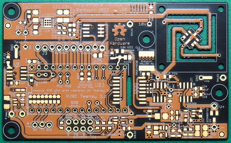
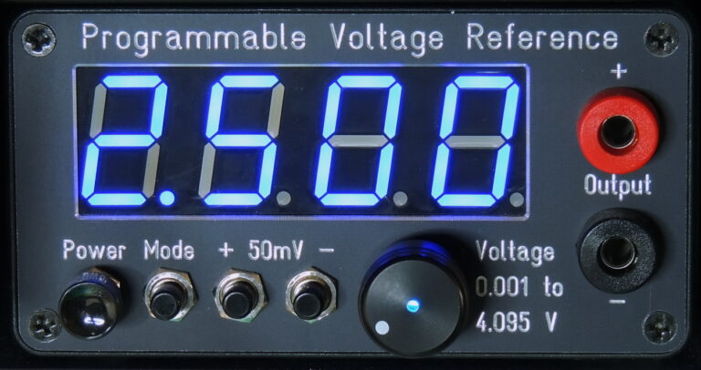
Barbouri’s Electronics Projects blog describes an updated Programmable Voltage Reference:

After five years and a few prototype revisions of the Version 2.12 Programmable Voltage reference, I decided it was time to update the project based on many requests and lessons learned from prototypes over the years.

The project remained dormant for several years while I worked on many other projects. After many requests for a 5 volt version of the PVR, I started working on an updated design again last year (2021) at a slow pace. The two main design factors were, providing an output up to 5 volts, and reducing the drift at the output from temperature and humidity changes.

What I ended up with after many iterations, was a 0.001 to 5.000 volt output version 3.14 of the Programmable Voltage Reference, with new components and and upgraded specifications.

Read more…

Programmable Voltage Reference, now in After Dark

Angry Storm Cloud Soldering Kit

From our friends at Alpenglow Industries:

This little cloud may look mean, but we promise it’s fun and easy to solder up!

This is a super fun and simple storm cloud blinky board. It has 3 self-flashing LEDs that act as the clouds lightning bolts! It also has an on/off switch and includes a CR2032 battery.

Why did you make it?

Robyn made this board for people to have a fun, easy project to learn how to solder. This is her second design and thought going with an angry storm cloud would be a fun opposite of the original happy rain cloud.

What makes it special?

This board was made using OSH Park’s After Dark Service so the black substrate and clear soldermask shows off the copper beautifully, check out the back! Please checkout Hackaday for solder instructions and more info! You can order 2 and follow our instructions on Hackaday on how to make them into a pair of flashy earrings!

Angry Storm Cloud Soldering Kit

AND!XOR’s DEF CON 29 Electronic Badge is an Assembly Puzzle

Hackday editor Mike Szczys reviews the latest #badgelife masterpiece from AND!XOR:

For years I’ve looked forward to seeing each new unofficial hardware badge that comes out of the #Badgelife powerhouse known as AND!XOR. A mix of new and interesting components, alternate-reality game, and memes, you never know what they’re going to throw down.

A bubble pack landed on my desk on Thursday with the newest offering, the AND!XOR electronic badge built for DEF CON 29, happening this weekend as a hybrid in-person and online conference. While each previous year upped the ante on complexity and manufacturing magic tricks, it’s no surprise considering the uncertainty of both the global pandemic and global chip shortage that they took a different tack. What we have here is a badge hacking puzzle that challenges you to just figure out how to put the thing together!

The boards themselves are obviously the “After Dark” treatment of OSH Park (and sure enough, their logo is on the back of the board). The iconic treatment uses black substrate (the board itself), clear solder mask to let the copper traces show through, ENIG plating for golden pads, and white solder mask.

AND!XOR’s DEF CON 29 Electronic Badge is an Assembly Puzzle

EZ Fan2 Tiny Raspberry Pi Fan Controller

Jeremy Cook created this tiny PCB for controlling small cooling fans or other motors:

What is it?

PCB originally designed to control cooling fans on Raspberry Pi boards, but can be used with other small motors or DC loads. Includes a flyback diode to safely dissipate inductive voltage spikes.

Can also work with Arduino and other such dev boards.Why did you make it?

Wanted a way to control cooling fans off of a Raspberry Pi. While some fans have PWM inputs, some do not and cannot normally be controlled. This transistor board works well with the GPIO fan control option in Raspberry Pi OS (which turns it fully on and fully off).

Not a full motor driver (i.e. it only drives in one direction) but can be used with other simple DC motors as well. Includes a resistor and flyback diode.

What makes it special?

It’s very, very small, even compared to a prior THT version. It should therefore be able to fit inside nearly any case. The optional 90º headers are even spec’d out to be low profile.

Boards come fully assembled with or without headers depending on the option selected, and appearance of the boards may vary. Options also available for female-female wires as needed, and/or clear heat shrink.

Read more on Tindie…

EZ Fan2 Tiny Raspberry Pi Fan Controller

5×10 PixelLeaf RGB Matrix

Add RGB light to your project with this PixelLeaf display from Oak Dev Tech on Tindie:

5×10 PixelLeaf RGB Matrix – SK6812mini RGB Matrix

What is it?

A small but bright RGB matrix sized at 5×10 to provide a nice wide matrix for your project. Compatible with Adafruit NeoPixel libraries and FastLED. This is made with the SK6812mini meaning you can rest assured that the display will remain bright even if there is fluctuations in supply voltage.

Why did you make it?

I thought it would be fun to make an RGB matrix display for small projects where standard displays might not fit right.

What makes it special?

It’s 1:2 ratio makes it perfect for long format projects that don’t need square displays, but ones that would be better for scrolling or smaller form factors.

5×10 PixelLeaf RGB Matrix

AtomIO Simplifies Your Breadboard UI

We’ve all been there, you hook things up to a breadboard, only to find that you need to figure out a simple LED indicator to see what’s going on, or have to use a wire or two as an input “button.” This is fine, but not really optimal. You can of course add actual buttons and switches, and perhaps cut down your LEDs to make them more presentable, but this takes up valuable space and time.

If you’d like a little shortcut to this problem, then the Atom IO may be just what you need. The device plugs in to the + and – rails of a breadboard, with 5 lines that connect to 3 LEDs, as well as 2 buttons. The LEDs are routed to the ground rail, so if you apply 2-ish volts, each will light up. The buttons are normally pulled low, but supply voltage from the positive rail when engaged.

Read more: AtomIO Simplifies Your Breadboard UI — Tindie Blog

AtomIO Simplifies Your Breadboard UI

Lucky Resistor: Let’s Print a Cat/Pet Feeding Device

From the Lucky Resistor blog:

The seventh part of this series is all about the sensor board. It hosts the position sensor and four fill sensors. Speaking of sensors sounds complex, but these are just pairs of IR-LEDs and phototransistors. All design files for the board are in the GitHub repository and if you missed one of the previous parts, look at the overview page.

Read more…

Lucky Resistor: Let’s Print a Cat/Pet Feeding Device

Attiny LED Letter Keychain

Alexisgm97 documents this LED keychain project on Instructables:

Attiny LED Letter Keychain

Today I am going to show you how to make a very cool LED keychain. To do this, we are going to use an ATtiny to make the LEDs blink and fade. This is going to help us to learn how to solder SMD components and also how to program an ATtiny.

You can also find the code here in case you want to modify it or even create a new one! This code has 4 modes: All on, slow blink, fade and fast blink that change every time we press the button and then it enters in sleep mode to save battery.

Once we have finished, we can carry our creation around with our keys as a keychain!

Are you ready? Enjoy!

Attiny LED Letter Keychain