Dexter the Companion Bot Wants To Give You Five

From Roger Cheng on Hackaday:

The main character of Dexter’s Laboratory is a genius child inventor who inspired a lot of fans to become makers and inventors in their own right. [Jorvon Moss] a.k.a. [Odd_Jayy] counts himself as one of them. A serial companion bot builder, his projects are constantly evolving. But every once in a while he pauses long enough to share construction details. Like how we can build our own monkey companion bot Dexter named after the cartoon.

A slightly earlier iteration of Dexter attended Hackaday Superconference 2019. Perched on [Odd_Jayy]’s back, Dexter joined in a presentation on companion bots. We’ve been a fan of his work since Asi the robot spider and several more robots have been posted online since. Recently at Virtually Maker Faire 2020, he joined [Alex Glow] and [Angela Sheehan] to talk about their respective experiences Making Companion Bots.

[Odd_Jayy] starts with sketches to explore how a project will look and act, striving to do something new and interesting every time. One of Dexter’s novelties is adding interactivity to companion bots. Historically people couldn’t do much more than just look at a companion bot, but Dexter can high five their fans! Sometimes the excited robot monkey ends up slapping [Odd_Jayy] instead, but they’re working through issues in their relationship. Everyone is invited to see rapid cycles of iterative improvements on Twitter and Instagram. As of this writing, a mini Dexter is underway with design elements similar to the “Doc Eyes” goggle project running in parallel. It’s always fun to watch these creations evolve. And by openly sharing his projects both online and off, [Odd_Jayy] is certainly doing his part to inspire the next wave of makers and inventors.

via Dexter the Companion Bot Wants To Give You Five — Hackaday

Quote

N64 Portable, Zelda Style!

From the Downing’s Basement blog:

Project 15: My Latest N64 Portable, Zelda Style!

I wish I could say that it hasn’t been two years since this project was commissioned…I also wish I could say this wasn’t the second time the job was completed…but if I didn’t have too, this beauty would have never existed. Kinda funny how that works.

But that said, after two years since the original agreement and a total remake of the original failure, Project 15 has come to light in the most beautiful portable console I’ve ever made. But not only has this been a technical achievement for me in many respects, but I’m very proud of the video I’ve made to accompany it.

You don’t have to scroll down very far in past posts to see what prompted this rebuild but at this point I can honestly say I’m glad it happened!

20200428_181806

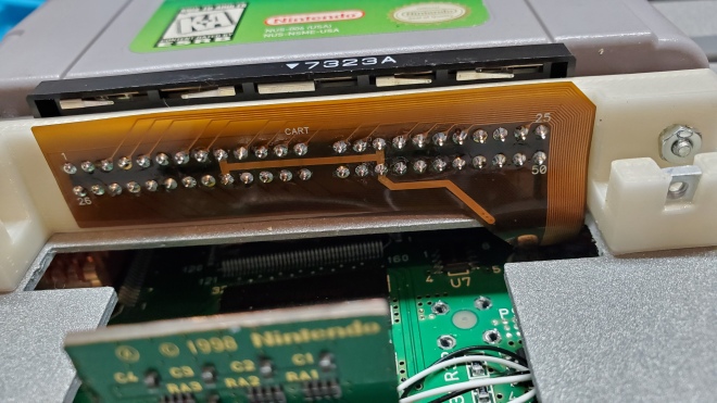
And on the subject of reliability, low volume FFC PCB’s have become available through services like OSH Park which have allowed some very time and space saving options that do wonders for the assembly.

Read more…

Quote

Adjustable Jig Eases PCB Stencil Alignment Process

PCB stencils make application of solder paste a snap, but there’s a long, fussy way to go before the paste goes on. You’ve got to come up with some way to accurately align the stencil over the board, which more often than not involves a jury-rigged setup using tape and old PCBs, along with a fair amount of finesse and a dollop of luck.

Luckily, [Valera Perinski] has come up with a better way to deal with stencils. The Stencil Printer is a flexible, adjustable alignment jig that reduces the amount of tedious adjustment needed to get things just so. The jig is built mostly from aluminum extrusions and 3D-printed parts, along with a bunch of off-the-shelf hardware. The mechanism has a hinged frame that holds the stencil in a fixed position above a platen, upon which rests the target PCB. The board is held in place by clamps that ride on threaded rods; with the stencil flipped down over the board, the user can finely adjust the relative positions of the board and the stencil, resulting in perfect alignment. The video below is mainly a construction montage, but if you skip to about the 29:00 mark, you’ll see the jig put through its paces.

Granted, such a tool is a lot more work than tape and spare PCBs, but if you do a lot of SMD work, it may be worth the effort. It’s certainly less effort than a solder-paste dispensing robot.

via Adjustable Jig Eases PCB Stencil Alignment Process — Hackaday

Quote

Surviving The Pandemic As A Hacker: Peering Behind The Mask

We’re now several months into the global response to the COVID-19 pandemic, with most parts of the world falling somewhere on the lockdown/social distancing/opening up path.

It’s fair to say now that while the medical emergency has not passed, the level of knowledge about it has changed significantly. When communities were fighting to slow the initial spead, the focus was on solving the problem of medical protection gear and other equipment shortages at all costs with some interesting yet possibly hazardous solutions. Now the focus has moved towards protecting the general public when they do need to venture out, and as society learns to get life moving again with safety measures in place.

So, we all need masks of some sort. What type to do you need? Is one type better than another? And how do we all get them when everyone suddenly needs what was once a somewhat niche item?

via Surviving The Pandemic As A Hacker: Peering Behind The Mask — Hackaday

Quote

Why Does Solder Smoke Always Find Your Face?


For some of us the smell of rosin soldering flux vaporizing from the tip of an iron as a project takes shape is as evocative as the scent of a rose on a summer’s day. We’ve certainly breathed enough of it over the years, as it invariably goes from the piece of work directly into the face of the person doing the soldering. This is something that has evidently troubled [AlphaPhoenix], who has gone to extravagant lengths to research the problem using planar laser illumination and a home-made (and possibly hazardous) smoke generator.

He starts with a variety of hypotheses with everything from a human-heat-driven air vortex to the Coandă effect, but draws a blank with each one as he models them using cardboard cut-outs and boxes as well as himself. Finally he has the light bulb moment and discovers that the key to the mystery lies in his arms coming across the bench to hold both iron and solder. They close off an area of lower-pressure dead space which draws the air current containing the smoke towards it, and straight into his face.  It’s something that can be combated with a small fan or perhaps a fume extractor, as despite some video trickery we have yet to master soldering iron telekinesis.

via Why Does Solder Smoke Always Find Your Face? — Hackaday

Quote

Hackaday Prize and Conservation X Labs Issue Design Challenges to Address Extinction Crisis

When most people think of extinct species, they likely imagine prehistoric creatures such as dinosaurs or woolly mammoths. Extinction is something you read about in history books, nature’s way of removing contestants in the great game of life. It’s a product of a cruel and savage world, and outside of a few remaining fringe cases, something that humanity’s advanced technology has put a stop to.

Unfortunately, the truth is far more complicated than that. The planet is currently going through its sixth major extinction event, and this time, it’s our fault. Humanity might not be willfully destroying the natural habitats of the plants, fish, birds, and other lifeforms that have been eradicated, but we’re responsible for it just the same. Humans are an apex predator unlike any the world has ever seen before, and the only force that can stop us is ourselves.

Founded in 2015, Conservation X Labs is devoted to doing everything it can to end this sixth wave of extinction. Unsatisfied with the pace of traditional conservation, they leverage technology and open innovation to develop unique new ways of combating the damage our species has done to life on this planet. After all, it’s the only one we’ve got.

We’ve partnered with this organization to help develop solutions to some of these problems. This includes an open call challenge that anyone can enter, and a Dream Team program that you can get involved with if you act quickly. Let’s take a look at what Conservation X Labs is all about, and what is involved with the challenges at hand.

THE CHALLENGE OF HACKING THE PLANET

With such a worthy goal and their embrace of out-of-the-box thinking, Conservation X Labs was a perfect partner for the 2020 Hackaday Prize. Saving species that have become endangered by human activity requires robust real-world solutions, but if they’re to have any chance at being adopted on a large scale, they need to be deployable at minimal cost and with the least amount of disruption as possible. That can be a difficult balance for large commercial entities to strike, but it’s the sort of thing that the hacking and making community absolutely excels at.

For the 2020 Hackaday Prize, Conservation X Labs has tasked competitors with developing innovative solutions for protecting marine life and combating invasive species. Building hardware that can survive the harsh ocean environment adds an extra dimension of challenge to these entries, and we’re excited to see how the submitted designs take it into account.

According to Sam Kelly, the Conservation Technology Program Manager at Conservation X Labs and mentor for this year’s Hackaday Prize, teams that want to tackle these challenges need to plan ahead if their design is to have any chance of surviving. “Between the salt, weather, pressure, and water, any solution needs to be ready for ingress and corrosion. It is also essential to consider the potential inaccessibility of any deployed device – for both maintenance and communication.”

Teams also have to make special considerations for the end-user. If you’re developing a device that needs to be operated by fishermen on a rocking boat in the middle of the ocean, a tiny touch screen probably isn’t going to work out very well. If it’s too difficult or time consuming to operate, then in all likelihood it just won’t get used.

via Hackaday Prize and Conservation X Labs Issue Design Challenges to Address Extinction Crisis — Hackaday

Quote

2020 Hackaday Prize Reveals Four Open Challenges and New Dream Team Program


The 2020 Hackaday Prize begins right now. Our global engineering challenge seeks solutions to real-world problems. If you like to come up with creative solutions to tough problems, four non-profits can use your help. We need hackers, designers, and engineers throughout the world to work on designs for conservation, disaster relief, renewable resources, and assistive devices.

via 2020 Hackaday Prize Reveals Four Open Challenges and New Dream Team Program — Hackaday

Quote

New Teensy 4.1 Arrives with 100 Mbps Ethernet, High-Speed USB, 8 MB Flash

It was only last August that PJRC released Teensy 4.0. At that time, the 4.0 became the fastest microcontroller development board on the planet, a title it still holds as of this writing — or, well, not exactly. Today the Teensy 4.1 has been released, and using the same 600 MHz ARM Cortex M7 under the hood, is now also the fastest microcontroller board. What the 4.1 brings to the table is more peripherals, memory, and GPIOs. While Teensy 4.0 used the same small form factor as the 3.2, Teensy 4.1 uses the larger board size of the 3.5/3.6 to expose the extra goodies.

The now slightly older Teensy 4.0 — released on August 7th of last year — is priced at $19.95, with the new 4.1 version offered at $26.85. It seems that the 4.1 isn’t intended as a replacement for the 4.0, as they serve different segments of the market. If you’re looking for an ultra-fast affordable microcontroller board that lives up to its Teensy name, the 4.0 fits the bill. On the other hand, if you need the additional peripherals broken out and can afford the space of the larger board, the not-as-teensy-sized 4.1 is for you. How big is it? The sample board I measured was 61 x 18 mm (2.4 x 0. 7″), not counting the small protrusion of the micro-usb jack on one end.

Let’s have a look at all the fun stuff PJRC was able to pack into this space.

100 MBPS ETHERNET

k41_ethernet

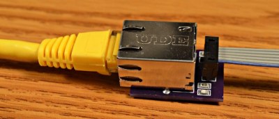
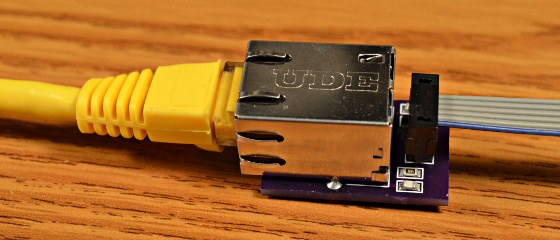
The big news is that Teensy 4.1 comes with 100 Mbps Ethernet support. To use the Ethernet port, you need to supply external magnetics and an RJ-45 jack. These were left off the board for obvious reasons — even using a jack with integrated magnetics (magjack), it wouldn’t fit on the PCB. Instead, a 6-pin header on the board can connect to an external interface. This also helps keep the price low for those who need the other features of the 4.1 without Ethernet connectivity.

PJRC will likely sell a DIY kit of the required parts in the future, but they don’t have a release date or pricing yet. For now, you can easily build your own using this OSH Park shared project. The parts list is in the project’s description, with the key part being the magjack, which will set you back around $2.55 in single quantities. Those building a board should note that this is an early version, and it turns out that only the 0.1 uF capacitor is necessary. Paul Stoffregen of PJRC told me that he just received a simpler PCB for testing, and will publish the design once it’s has been thoroughly verified.

The Ethernet port is capable of full 100 Mbps speed and supports the IEEE 1588 precision time protocol, which allows synchronization of clocks to within 100 ns over wired connections, enabling some very interesting possibilities. But, aside from that, just the inclusion of Ethernet on a microcontroller board is a big deal. Before this, you basically had two choices if you needed this kind of connectivity: use a powerful single-board-computer like a Raspberry Pi with all the latency and headaches the required operating system brings for doing low-level or real-time tasks, or add a slow SPI-interfaced Ethernet board to an existing microcontroller. Instead, you can now use the 600 MHz Cortex-M7 on this new board to run high-bandwidth, low-latency embedded applications without fighting an OS.

via New Teensy 4.1 Arrives with 100 Mbps Ethernet, High-Speed USB, 8 MB Flash — Hackaday

Quote

Open Source Pick and Place Has a $450 BOM Cost

Give your grizzled and cramped hands a break from stuffing boards with surface mount components. This is the job of pick and place machine, and over the years these tools of the trade for Printed Circuit Board Assembly (PCBA) have gotten closer to reality for the home shop; with some models diving below the $10,000 mark. But if you’re not doing it professionally, those are still unobtanium.

The cost of this one, on the other hand, could be explained away as a project in itself. You’re not buying a $450 shop tool, you’re purchasing materials to chase the fever dream of building an open source pick and place machine. There are two major parts here, an X/Y/Z machine tool that can also rotate the vacuum-based parts picker, and the feeders that reel out components to be placed. All of this is working, but there’s still a long road to travel before it becomes a set and forget machine.

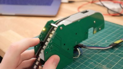
The rubber hits the road in two ways with pick and place machines: the feeders, and the optical placement. The feeders are where [Stephen Hawes] has done a ton of work, all shown in his video series that began back in January. The stackup of PCBs and 3D-prints hangs on the front rail of the gantry assembly, is adjustable for tape widths, and uses an interesting PCB encoder wheel and worm-gear for fine-tuning the feed. [Stephen’s] main controller board, a RAMPS shield for and Arduino Mega that runs a customized version of Marlin, can work with up to 32 of these feeders.

via Open Source Pick and Place Has a $450 BOM Cost — Hackaday

Quote