Many devices have a USB-C connector to charge or power them. This is very convenient given the popularity of USB-C, its reversible cable design, and sturdy, compact design.
However, some devices will not draw power when using a USB-C-to-C cable connected to a spec-compliant charger, but will when using a USB-A-to-C cable. The USB-C specification requires upstream facing ports (UFPs), the port of the device receiving power, to connect pull-down resistors to the configuration channel (CC) pins. These missing pull-down resistors are a common reason why devices can draw power with A-to-C cables but not C-to-C ones.
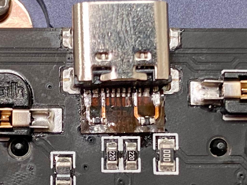
Wouldn’t it be great to be able to add these resistors and enable USB-C-to-C power? This mod does just that. It is a small flex PCB with pads for two 5.1kohm pull-down resistors between CC1 and CC2, respectively, and GND.
This is a mod to add USB-C-to-C charging to devices without it. Very impressed by @oshpark's flex PCB service. The PCB needs to be dead accurate to solder to the USB connector pins (0.3mm wide) and the installed mod works perfectly.
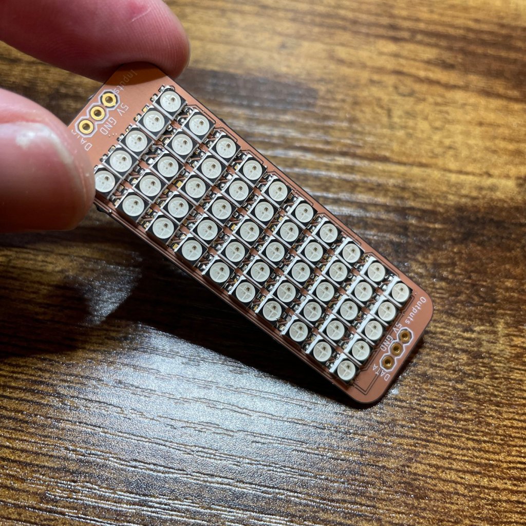
A small but bright RGB matrix sized at 5×10 to provide a nice wide matrix for your project. Compatible with Adafruit NeoPixel libraries and FastLED. This is made with the SK6812mini meaning you can rest assured that the display will remain bright even if there is fluctuations in supply voltage.
Why did you make it?
I thought it would be fun to make an RGB matrix display for small projects where standard displays might not fit right.
What makes it special?
It’s 1:2 ratio makes it perfect for long format projects that don’t need square displays, but ones that would be better for scrolling or smaller form factors.
Any video that starts with a phase diagram has instantly earned our attention. Admittedly, we have a pretty low bar for that kind of stuff, but eye candy aside, [Robin Debreuil]’s quick outline of his technique for desoldering with the help of bismuth is worth watching…
Today we are excited to announce that the open hardware journal HardwareX is integrating OSHWA certifications into their paper submission process.
HardwareX is an open access journal that focuses on free and open source designing, building, and customizing of scientific hardware. It has long used the Open Source Hardware Definition as a requirement for submissions. Now HardwareX is also integrating the OSHWA hardware certification program into the paper submission process.
First, HardwareX has updated its guide for authors to encourage (although not require) authors to certify their hardware for open source compliance before, during, or after submitting to HardwareX. This is a win for authors and for HardwareX. Authors can use the certification process to make sure that their hardware meets the Open Source Hardware Definition. Certification is often an iterative process where OSHWA helps creators meet all of the Definition’s requirements. HardwareX can rely on the OSHWA certification to confirm that hardware complies with the Definition, freeing up resources to review the papers themselves.
Second, OSHWA and HardwareX are standardizing ways to connect HardwareX articles to the Certification Directory. HardwareX will include OSHWA certification UIDs in their specification tables for articles that include certified hardware. Creators can update their certification directory listing with the “#HX” tag in the project description, and add a link to the HardwareX manuscript.
As the open hardware community grows, so too do our institutions. We look forward to finding new ways to collaborate with all of the parts of the community in the future. If you would like to connect with the certification program, please reach out at [email protected], check out our certification program API, or just certify your own hardware directly!
A few years ago [Mechatrommer] got one of the low-cost Aneng Q1 multimeters and has converted it into a bench top meter. He first tried and failed to do an LCD modification and set it aside. It remained in a storage box until he needed another meter to repair his rubidium frequency standard. Finding that off-the-shelf bench multimeters were literally off-the-shelf — they were too deep for his bench — he decided to take matters into his own hands.
A hot air station is one of the standard tools for working with surface-mount electronics, mostly in the context of rework to fix problems rather than initial assembly. In addition to manuals for individual pieces of equipment, there are guides like this one from Sparkfun. My projects haven’t really needed me to buy one, though that’s debatable whether that’s a cause or an effect: perhaps I design my projects so I don’t need one, because I don’t have one!
Either way I knew some level of dexterity and skill are required to use the tool well, and the best way to get started is to start playing with one in a non-critical environment. Shortly before the pandemic lockdown, I had the opportunity when Emily Velasco offered to bring her unit to one of our local meetups for me to play with. I had a large collection of circuit boards removed from tearing down various pieces of equipment. I decided to bring the mainboard from an Acer Aspire Switch 10, which was a small Windows 8 laptop/tablet convertible that I had received in an as-is nonfunctional state. I was able to get it up and running briefly but I think my power supply hack had provided the wrong voltage. Because a few months later, it no longer powered up.
If you are working on anything IoT-related, the first thing you will need is connectivity.
For anything even moderately distributed that also has to run on batteries, this translates to incorporating hardware that enables you to send and receive messages using low-power radio access technologies like LTE-M or NB-IoT.
Since these are mobile network technologies, you will also need a SIM card and subscription.
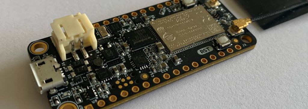
Jared Wolff has designed a really nice and small IoT development board, namely the nRF9160 Feather. It measures 21x53mm in size without the antennas and should be easy to incorporate in any IoT prototype.
Busy people who already have digital design experience and want to learn how to make a digital ASIC and apply to either the Google sponsored free shuttle or Efabless $10k shuttle.
You can bring some digital designs already simulated or tested on an FPGA. We have 2 example designs you can use if you have nothing handy.
You will need to have a reliable internet connection, webcam, headset and the class VM installed and tested.
Outcome
Basics of using OpenLANE ASIC flow to convert HDL to GDS.
Understanding of Caravel application harness
How to make a submission to Efabless to take part in the free shuttle program.






 OSH Park
