I’m very happy to have this opportunity. I’ve done a lot of science communication and always really enjoyed it. This course combines my love of electronics and teaching. The demand for tickets is helping me continue my study of Open Source ASIC tooling, contribute back to the community and help spread this experience to people who, like me, would never have thought that they’d one day get to make their own chips.
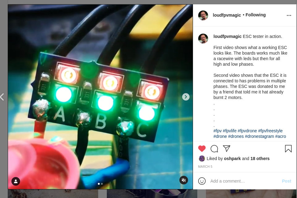
For many in the RC community, blowing up an Electronic Speed Controller (ESC) means one thing: throwing it away and buying another one. However, if you’re regularly pushing the limits or simply hate waste, fixing failed units is an option. To assist in this task, [LouD] built an ingeniously simple ESC tester.
The board is designed to be wired in parallel with a brushless DC motor when hooked up to an ESC. The board packs two LEDs per phase, wired in opposite directions. Thus, current flow in both directions can be visualised on a phase-by-phase basis. If everything is operational, the red and green LEDs on each phase should glow evenly as the throttle is ramped up. However, if there are problems, it will be readily apparent as the blinking becomes erratic or one or more LEDs fails to light at all.
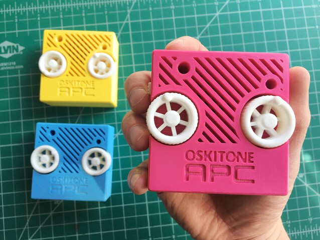
A decapitated robot head? An extraterrestrial communicator? A specter summoner?
Nope (and yep!), it’s an APC!
Just like the other Oskitone projects, it’s a 3D-printed electronic musical ~instrument, designed in Kicad and and OpenSCAD, Open-Source, and just plain ol’ annoying fun.
Eakins cameras have become a relatively popular, relatively inexpensive choice for electronics hobbyists to inspect their small-scale work. The cameras have a USB port for a mouse and overlay a GUI on the HDMI output for controlling the camera’s various settings and capturing images to the SD card. Using the mouse-based GUI can feel clunky, though, so users have already endeavored to streamline the process to fit better in their workflow. [charliex] decided to take streamlining a few steps further.
One issue in microscope photography is that microscopes have an extremely tight focus plane. So, even at the minuscule scales of an SMD circuit board, the components are simply too tall. Only a sub-millimeter-thick layer can be in focus at a time. If you take just a single image, much of what you want to see will be lost in the blurry distance. Focus stacking solves this problem by taking multiple pictures with the focus set at different depths then combining their focused bits into a single sharp image.
This takes care of the focus issue, but even the most streamlined and intuitive manual controls become tedious given the multitude of pictures required. So [charliex] searched for a way to remotely control his camera, automating focus stacking and possibly even full PCB scans.
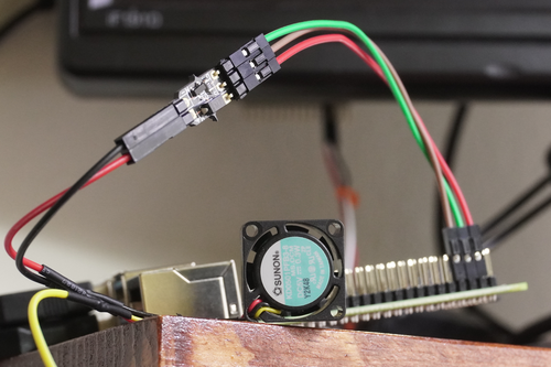
While passive cooling options are often good enough to avoid overheating and thermal throttling–and I do love a ridiculously oversized heat sink–at some point you’ll need to think about using a cooling fan. The problem is that the Raspberry Pi’s GPIO pins don’t supply enough power to get one going.
One alternative is to hook the fan up to a 5V and ground pin, and just have it run continuously. However, this seems slightly wasteful power-wise, and potentially quite annoying. As outlined previously, you can also use a transistor and temperature-reactive Bash script to turn a fan on and off via the processor’s temperature. Things have changed since mid-2020, however, and Raspberry Pi OS now has this functionality built-in. Making things even more convenient, if you’re using a fan with a PWM input, you don’t actually need to add an extra transistor!
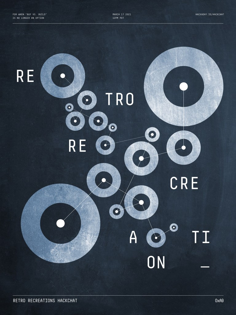
Nostalgia seems to be an inevitable consequence of progress. Advance any field far enough into the future, and eventually someone will look back with misty eyes and fond memories of the good old days and start the process of turning what would qualify as junk under normal conditions into highly desirable collectibles.
In some ways, those who have been bitten by the computer nostalgia bug are lucky, since the sheer number of artifacts produced during their period of interest is likely to be pretty high, making getting gear to lovingly restore relatively easy. But even products produced in their millions can eventually get difficult to find, especially once they get snapped up by eager collectors, leaving the rest to make do or do without.
Of course, if you’re as resourceful as Tube Time is, there’s another alternative: build your own retro recreations. He has embarked on some pretty intense builds to recapture a little of what early computer enthusiasts went through trying to build useful machines. He has built replicas of early PC sound cards, like an ISA-bus AdLib card, its MCA equivalent, and the “Snark Barker”— or is it the “Snood Bloober”? — which bears an uncanny resemblance to the classic Sound Blaster card from the 1980s.
Tube Time will join us for the Hack Chat this week to answer questions about all his retro recreations, including his newest work on a retro video card. Be sure to bring your questions on retro rebuilds, reverse engineering, and general computer nostalgia to the chat.
Hard to believe that it’s been nearly 12 years since I started Modding but more specifically since I learned how to solder. Without a doubt it has been one of most useful skills to come from the hobby, even if I’m still not particularly *great* at it. But for all that time and all the projects have come out of the basement, every single one of them had at least some kind of contact with the same soldering iron I got when I started.
So after speaking with some fellow modders and community members, it seemed there were two options for high performance, mid-range soldering stations. These being the Hakko FX888D and the KSGER T12. I’d considered both options carefully, but in the end I was impressed with the multiple layers the KSGER had for settings. Instead of just heat up/down option, there was a whole lot of programming options built in that I’m still learning.
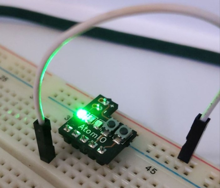
We’ve all been there, you hook things up to a breadboard, only to find that you need to figure out a simple LED indicator to see what’s going on, or have to use a wire or two as an input “button.” This is fine, but not really optimal. You can of course add actual buttons and switches, and perhaps cut down your LEDs to make them more presentable, but this takes up valuable space and time.
If you’d like a little shortcut to this problem, then the Atom IO may be just what you need. The device plugs in to the + and – rails of a breadboard, with 5 lines that connect to 3 LEDs, as well as 2 buttons. The LEDs are routed to the ground rail, so if you apply 2-ish volts, each will light up. The buttons are normally pulled low, but supply voltage from the positive rail when engaged.
As its name implies, the AtomIO is very small, allowing you to squeeze it into limited breadboard space. While you could certainly take care of any of these tasks yourself, it looks like a great way to clean things up, and perhaps even save a little time! Default LED colors are green, yellow, and red, but you can request customizations if you so choose.
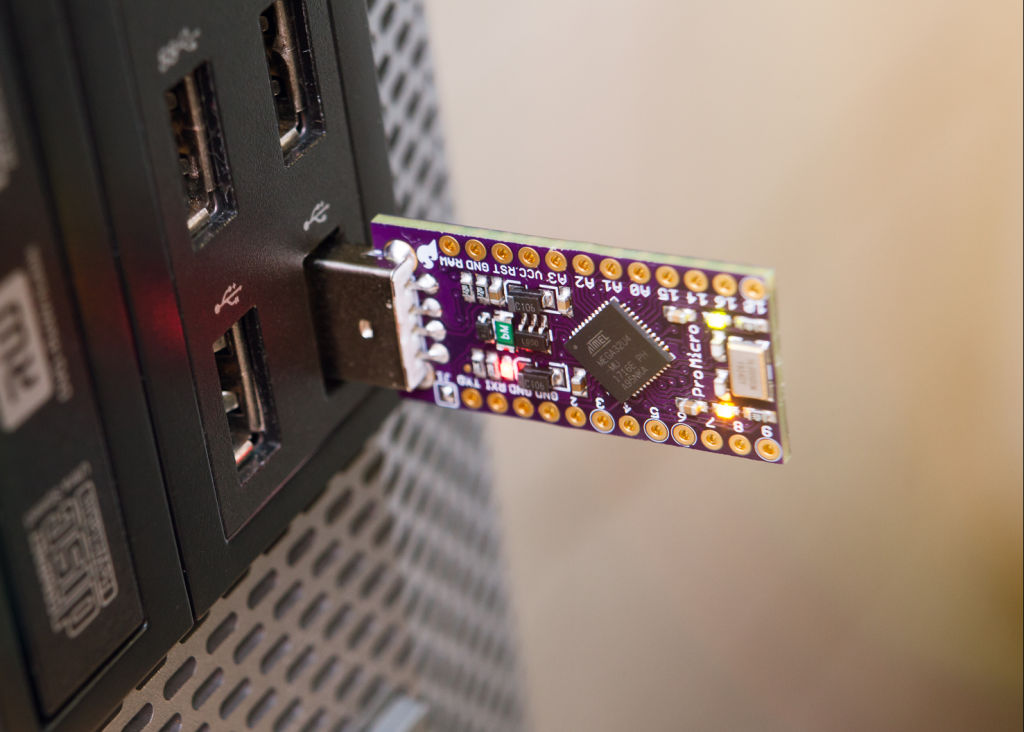
Lately I’ve been working on a project that will use an Arduino to translate signals from a wireless receiver into USB HID inputs for my computer. I had the perfect microcontroller picked out too: the SparkFun Pro Micro, which uses the Arduino-compatible ATmega32U4 and has enough I/O pins for my project and then some. There’s just one problem – the Pro Micro doesn’t have a USB-A port to plug directly into a computer! Instead it has a micro USB-B port, and requires a short cable to connect it to a PC.
Luckily for me the Pro Micro, like many of SparkFun’s designs, is open source and licensed under Creative Commons Share-alike. So I decided to dive in and modify the design to create my own version of the Pro Micro with a USB-A port!
As mildly exotic silicon has become cheaper and the ingenuity of hardware hackers has been unleashed upon it, it’s inevitable that some once-unattainably expensive instruments will appear as cheap modules from China. The LTDZ spectrum analyser on the bench today covers 35 MHz to 4.4 GHz, and has a USB interface and tracking source. It has been available from all the usual outlets for a while now either as a bare PCB or in a metal box about the size of a pack of cards.
We’ve already taken a look at the $50 VNA, and this time it’s the turn of the $30 spectrum analyser, in the form of a little device that I succumbed to while browsing Banggood.
I ordered one, along with an attenuator and RF bridge for SWR measurements, and after the usual wait for postage my anonymous grey package arrived and it was time to give it a look and consider its usefulness. It’s a design derived from one published in Germany’s Funkamateur (“amateur radio”) magazine early in the last decade, and unscrewing the end plate to slide out the board from its extruded enclosure we can see what makes it tick.