PixelWing takes flight

Our friends at Oak Development Tech designed this WiFi + RGB matrix display which combines the power of ESP32-S2 and SK6812mini:

PixelWing ESP32-S2 RGB Matrix

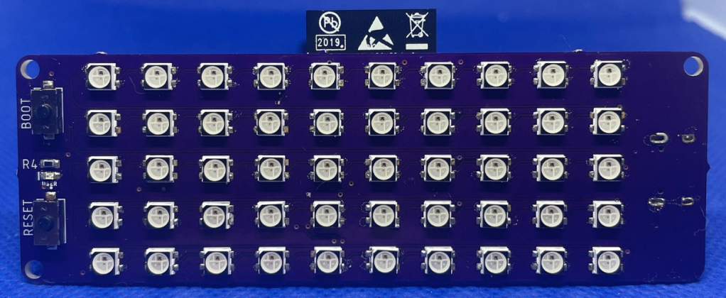
The PixelWing Matrix is a powerful ESP32-S2 RGB Matrix Display board that allows you to make a simple connected display, data logger, or environmental indicator. The PixelWing features USB-C power, a 5×10 RGB Matrix Display using SK6812mini Addressable LEDs that are compatible with Adafruit NEOPIXEL Libraries!

In addition to this, the PixelWing provides a quick access I2C JST connector that is compatible with Qwiic and Stemma QT connectors allowing you to connect all your favorite Adafruit and Sparkfun sensor breakouts.

All of this is combined with Circuit Python support making it easy to get programming on your project.

PixelWing takes flight

[0x1F] OSH Park in Space 💜🛰️

Our newest sticker features OreSat,

Our newest sticker 0x1F honors OreSat:

Small educational satellites called CubeSats have been launched by dozens of universities and countries around the world. But so far Oregon has yet to fly our very own artisanally hand-crafted CubeSat. We’re changing that!

We currently have two satellite missions in the works. Both rely on the fully open source “OreSat” bus which we’re offering as an inexpensive (for a satellite!) “DIY” platform for designing and building your own CubeSat.

We’re based out of the Portland State Aerospace Society (PSAS) at Portland State University, but we have collaborators at most other Oregon universities! Here’s a bit more about us.

Here’s how to get involved. You can also follow our development progress on github; OreSat is a completely open source project.

Finally, please also consider donating to support Oregon’s first satellites!

[0x1F] OSH Park in Space 💜🛰️

Last Chance to Reimagine Supportive Tech for the Hackaday Prize is This Weekend

This is the final weekend to enter your supportive tech project in the 2021 Hackaday Prize. To goal is to find ways to make building or using electronics easier.

Accessibility is one obvious approach to this challenge. But you can also consider the example of reference designs in datasheets. Manufacturers know you don’t want to re-invent the wheel to use their switch-mode power supply so they give you information on how to lay it out on the PCB and what parts to choose. Now take that idea and run with it. This could be a modular design that takes the wizardry out of building electronic projects. But it could just as easily be a aimed at the end user — perhaps lab equipment that’s normally expensive and requires expertise to operate but you’ve reimagined it to have most of that expertise built in.

Need some more help figuring out what this is all about? Let’s look at some of the projects that have already been entered. With devices all around us that have superb cameras and dazzling screens, [Timo] realized it wouldn’t take much to turn one into an inspection microscope, which is just what’s been done with nothing more than a 3D-printed stand and a desk lamp.

[Alain] put his electronics knowledge, and the availability of cheap modules, to great use for his non-verbal son. The PECS Communication Board has a grid of sixteen images, each is a button to act as input. He makes the point that tablet apps exist for this, but durability and cost are both issues that his approach helps address.

There are already a ton of other great entries for this round of the Hackaday Prize, but it wouldn’t be complete without yours. Ten will be chosen to receive $500 each and move on to the finals with a $25,000 grand prize on the line. Start your project right now on Hackaday.io and use the left sidebar drop down menu on your project page to enter it.

Read more from Hackaday…

Last Chance to Reimagine Supportive Tech for the Hackaday Prize is This Weekend

Oskitone launches the Scout synth kit

Oskitone has launched the Scout, an Arduino-compatible, monophonic, square wave synth:

  • 17 keys
  • Custom PCB and 3D-printed hardware
  • Satisfying “clicky” tactile switches
  • Built-in amplifier, speaker, and output jack
  • Powered by 3 AAA batteries
  • Open-source and ready to be hacked. Re-programmable with FTDI cable (not included)
Oskitone launches the Scout synth kit

Gladys West Modeled the Earth So That We Can Have GPS

Al Williams writes on Hackaday:

The name Gladys West is probably unfamiliar, but she was part of creating something you probably use often enough: GPS. You wouldn’t think a child who grew up on a sharecropping farm would wind up as an influential mathematician, but perhaps watching her father work very hard for very little and her mother working for a tobacco company made her realize that she wanted more for herself. Early on, she decided that education was the way out. She made it all the way to the Naval Surface Warfare Center.

While she was there she changed the world with — no kidding — mathematics. While she didn’t single-handedly invent satellite navigation, her work was critical to the systems we take for granted today.

Read more on Hackaday…

Gladys West Modeled the Earth So That We Can Have GPS

Hello FPGA Summer Giveaway

From our friends at Crowd Supply:

Curious about FPGAs but not sure where to start? We’ve got you covered! We’re teaming up with Crowd Supply, OSH Park, and Mouser to give away 30 Hello FPGA kits this summer and cover prototyping costs for up to five new shield designs.

Design a new Arduino shield for your Hello FPGA kit:

We will select up to five designs of a new Arduino shield for use with a Hello FPGA kit. Limit one proposal per person. Submit proposals with links to documentation via our contact form no later than Sunday, September 12, 2021 at 11:59 PM PDT. Winners will be announced on Friday, September 17, 2021. Winners will receive FREE PCB fabrication from OSH Park and parts from Mouser Electronics for prototypes of their design. Winners commit to submitting a video demonstrating a prototype of their proposed shield design in action no later than Tuesday, November 30, 2021. Selection of winners is at our discretion and will be based on the plausability of the proposed shield, completeness of the design, and the extent to which the new shield showcases the features of the Hello FPGA kit.

Read more…

Hello FPGA Summer Giveaway

Practical Print Makes iPad a Magnificent Eye Piece

Be it the ever shrinking size of components, the miniscule size of the printing on such pieces, or the steady march of time that makes visits to the optometrist an annual ritual, many of us could use some assistance when things start getting fuzzy at the workbench. Arm-mounted LED magnifying lenses can be a handy helper. Zooming in on a macro photo on a smartphone is also a common option that we’ve used many times.

[Timo Birnschein] started down a similar path when he realized that his iPad Pro comes with an app called simply “Magnifier”. A 12” iPad isn’t exactly the most convenient device to hold while trying to solder small parts, so he spent some time designing and 3D printing a specialty iPad stand that he calls a “Quick and Dirty High Performance EE Microscope.” We call it a magnificent tool hack!

Rotating the iPad diagonally so that the camera is closest to the subject leaves plenty of room to work and makes great use of the available screen space. [Timo] reports that at 50% magnification the 12” screen makes even 0603 SMD parts easy to read. Now he rejoices to have more to do with his iPad than watching YouTube and reading Hackaday- although we don’t know why you couldn’t do both.

The STL files have been released on Thingverse for your experimentation. [Timo] notes that he’d like to add an LED ring to brighten things up, and a fume extractor to protect the delicate lens on the iPad. We have to wonder if some plastic wrap over the lens might produce the same effect at almost no cost. Whatever [Timo] decides to do, we’re sure it’ll be brilliant.

Read more on Hackaday…

Practical Print Makes iPad a Magnificent Eye Piece

Circuit Shorts: Take on Those PCB Ridges

Saar Drimer writes about an interesting PCB technique:

When I ran the Boldport Club, I arranged a few community pub meets. It was a great way to meet people from the larger community and to see and hear what they’d been working on. In one of those meets, I serendipitously told Mike Harrison about what I’d been designing: an object that required interconnecting pieces of PCBs. Mike, with his extensive electronics installation experience, gave me a wonderfully effective tip: add small ridges along the slots on both pieces that are meant to be put together.

Getting the thicknesses of PCBs right is tricky. Firstly, PCBs normally have a 10% thickness tolerance and another tolerance for the slot/cutout routing. Secondly, the actual thickness depends on the design and on what’s at the surface of where it matters ─ copper, plating, finish, soldermask, silkscreen. So the variation in thickness from ‘nominal’ (0.8 mm, 1.55 mm, etc.) can be significant. We can’t keep experimenting until we get it right either; it’s expensive and somewhat pointless because of the tolerances. Adding ridges allows us to hedge our bets with a single go.

Read more…

Circuit Shorts: Take on Those PCB Ridges

Smart Home Power Line Communications Demo Board

JARViE created this dev board to create power line communications projects and products:

The JARViE PLM Demo Board offers users a simple and low-cost entry point into learning about Smart Home technology. Couple this modem with a microcontroller to bidirectionally communicate with other devices or systems over AC or DC power lines. Applications include lighting control, home appliance control, energy/heating control and up to 3,000 feet data transmission home power networks.

Each Demo board has an NXP TDA5051a powerline modem IC. This modem takes in a digital message from an MCUs UART bus, like an Arduino UNO, and translates this digital message into an equivalent analog message. Additional circuitry on the demo board sends the analog message over the 120/240VAC of your home, if the demo board is connected to a home outlet. Ideally, the analog message will be broadcasted across all the 120/240VAC wires of your home (to all home outlets), so another demo board connected to another home outlet will hear this message. The demo board has special filtering to only receive messages sent by other powerline modem demo boards and reject all other noise or communications between non-demo board devices. Once a demo board receives an analog message sent over the home power lines, it converts it to an equivalent digital message and sends it to an MCU over its UART bus. Additionally, the demo boards can communicate over DC powerlines as well.

Read more on Tindie…

Smart Home Power Line Communications Demo Board

uSMD shrinks soldering challenge down to BGA

The uSMD designed by Arthur Benemann in KiCad shrinks The Maker’s Box SMD Challenge down to a 555 in 8-UFBGA package and a 008004 cap:

A highlight of last year’s Hackaday Remoticon was a soldering competition that had teams from around the world came together online and did the well-known MakersBox SMD Challenge kit in which a series of LED circuits of decreasing size must be soldered. The Hackaday crew acquitted themselves well, and though an 01005 resistor and LED certainly pushes a writer’s soldering skills to the limit it’s very satisfying to see it working. Lest that kit become too easy, [Arthur Benemann] has come up with something even more fiendish; his uSMD is a 555 LED flasher that uses a BGA 555 and a selection of 008004 small components.

The trick with an 01005 is to heat not the tinned and fluxed solder joint, but the trace leading up to it. If components of that size can be mastered then perhaps an 008004 isn’t that much smaller so maybe the same technique might work for them too. In his tip email to us he wrote “Soldering 008004 isn’t much worse than a 0201, you just need magnification“, and while we think he might be trolling us slightly we can see there’s no reason why it shouldn’t be do-able. Sadly he doesn’t seem to have made it available for us to buy and try so if you want to prove yourself with a soldering iron you’ll have to source the PCBs and parts yourself. Still, we suspect that if you are the type of person who can solder an 008004 then that will hardly be an onerous task for you.

Read more on Hackaday…

uSMD shrinks soldering challenge down to BGA