
7 LED’s, 2 Pins – beat that, Charlieplexing
[Tim]’s Dice10 is an exercise in minimalism. [Tim] upped the game by using just two GPIO pins to drive the seven LED’s for the dice

[Tim]’s Dice10 is an exercise in minimalism. [Tim] upped the game by using just two GPIO pins to drive the seven LED’s for the dice
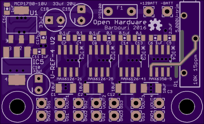
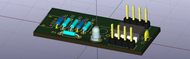
Barbouri has updated his voltage reference board design:
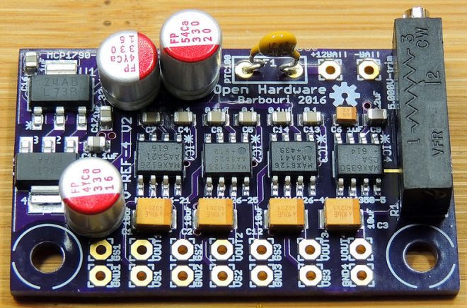
This is my version 2 board update, which incorporates supply voltage regulation, over-current protection, and trimmer for the 5.000 volt reference all on the same board.
The new board uses a LM2937IMPX-10, which is a positive linear voltage regulator IC with a 10V output at 400mA in a SOT-223-4 package.
Barbouri has shared project the project on OSH Park:

VR is going to be the next big thing in five to seven years, and with that comes the problem of what the controllers will look like. The Vive and PS Move are probably close to what the first successful consumer VR setup will look like, but there’s plenty of room for experimentation. [ShinyQuagsire] decided to…
Thanks to facelesstech for tweeting this design tip:

svg2mod by mtl is a small program to convert Inkscape SVG drawings to KiCad footprint module files:
There didn’t seem to be a good way to get vector graphics into Pcbnew, so I wrote a small utility that uses an existing SVG library to read files, and then writes them out as KiCad modules.
The project is hosted on GitHub:
It uses cjlano’s python SVG parser and drawing module to interpret drawings and approximate curves using straight line segments. Module files can be output in KiCad’s legacy or s-expression (i.e., pretty) formats. Horizontally mirrored modules are automatically generated for use on the back of a 2-layer PCB.

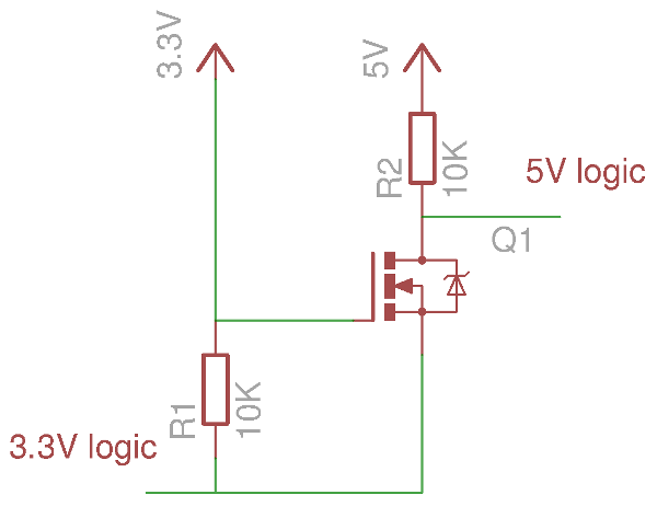
If your introduction to digital electronics came more years ago than you’d care to mention, the chances are you did so with 5V TTL logic. Above 2V but usually pretty close to 5V is a logic 1, below 0.8V is a logic 0. If you were a keen reader of electronic text books you might have…
Carlos Vadillo and Bx Dawes created the GlowSaber project to help kids in Alameda learn about physics, engineering and programming:

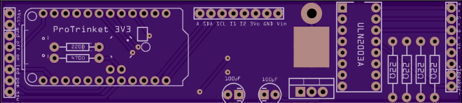
Building the GlowSaber main board
All the logic, sound and light effects of the GlowSaber are performed by a small microprocessor board. In this tutorial I will explain, step by step how to put together the main board of a GlowSaber.
One premise that I had while designing the GlowSaber was that I should be able to build all of it with tools that I already have. That limited the materials I could choose to those that I could cut, drill and glue with just the basic tools:

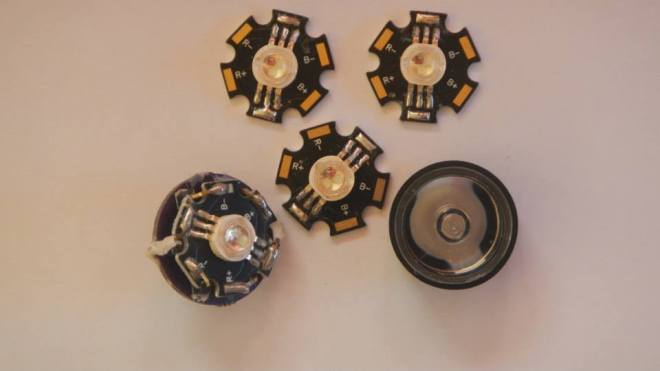
The GlowSaber uses a Vollong 3 watts RGB LED. It is very bright and more than enough to light the length of the blade. When designing the GlowSaber I found that I needed a way to connect the LED to the main PCB and I designed a LED break out
How to use a potentiometer to change the behavior
The GlowSaber has a switch assembly, that controls the on/off functions. It also has a LED to show that the GlowSaber is ready to start, and finally has a small 1 kΩ potentiometer. The following is a schematic of the switch assembly:

cvadillo has shared the board on OSH Park:
![]()
askoog89 saw a major flaw with many LED watches – you have to press a button to see the time:
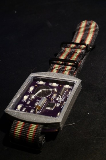
I tried fix that problem by using a tilt switch to active the LED showing the time when tilt your arm to look at the watch
The watch uses the low power MSP430G2211 MCU from Texas instruments to control the LED and mesure the time with the help of a 32kHz watch cristal. The MCU sleeps most of the time only waking up ones a second to count up the time and check if the tilt switch is active. To show the time the watch uses 12 charlieplexed orange LEDs.

2016 has been a great year! Over 20 workshops, lectures, seminars, courses. One Indiegogo campaign. Hundreds of people started using the Tinusaur platform. So, what’s next? Our Q1 goal: Launch new Indiegogo campaign in February to produce 1000 Tinusaur kits and bring the cost down to $2 per basic kit. This will make our boards […]
via Moving forward with the Tinusaur Project in 2017 — The Tinusaur
Extreme Electronics designed this easy-to-build solenoid engine:
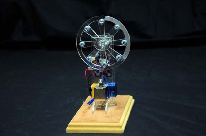
I’ve always loved solenoid engines. The first one I built was many,many years ago out of Mechano. Many others have followed since, But they always ran badly and only for a short while as the accuracy of the construction medium was poor. I am not a metal worker, making a “proper” engine out of cast pieces is out of my (and many other peoples) capabilities.
With modern laser cutting it is easy to make accurate components, it is relatively cheap and fairly quick.
So the Acrylic Solenoid Engine came into being

The initial driver is using a small PIC 12F675 and and an IR detector to give me pulse timing information from the solenoid. I went the IR sensor route rather than a mechanical switch so there was no rubbing parts that could wear as acrylic is rather soft. To get a good timing signal aluminum foil is placed on one side of the flywheel to give a good reflection back to the IR emitter receiver pair on the PCB.
Brian Benchoff of Hackaday continues his series of posts about KiCad:
This is the third and final installment of a series of posts on how to create a PCB in KiCad, and part of an overarching series where I make the same schematic and board in dozens of different software tools


