Fibonacci64 Micro

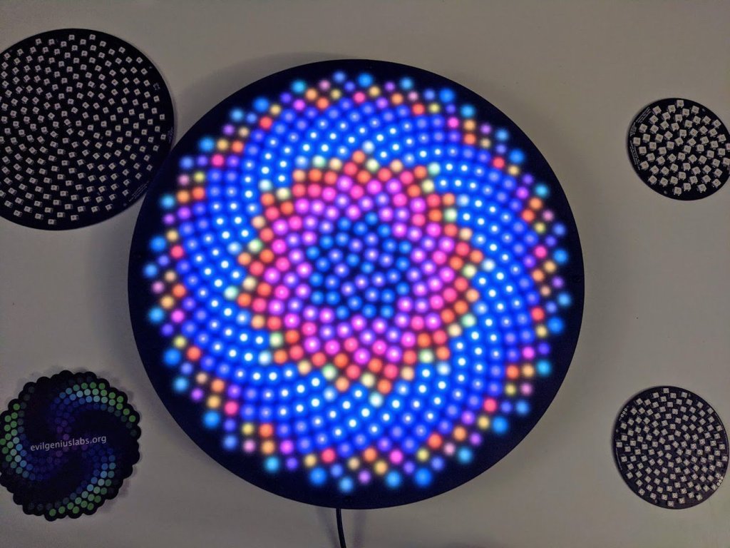
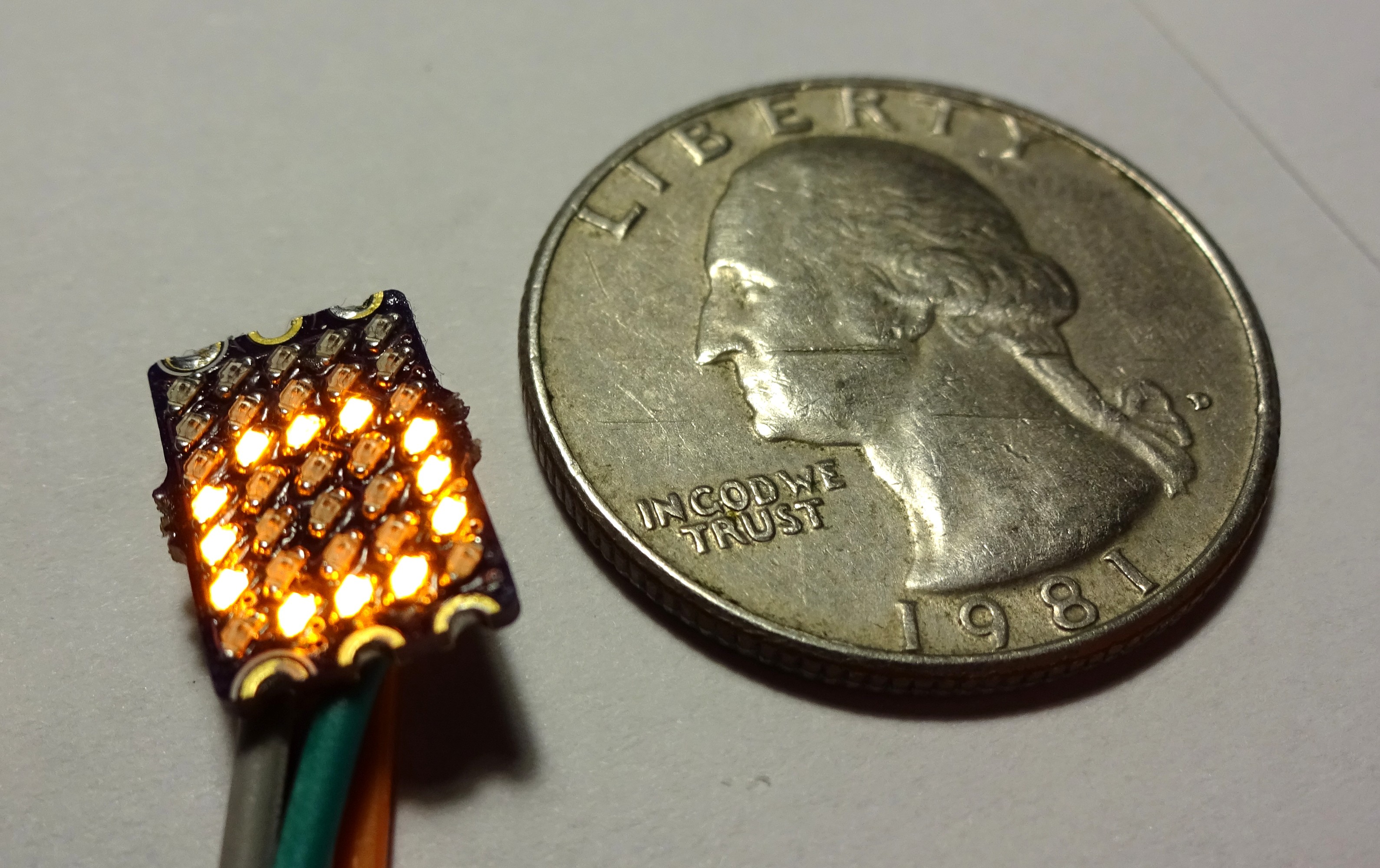
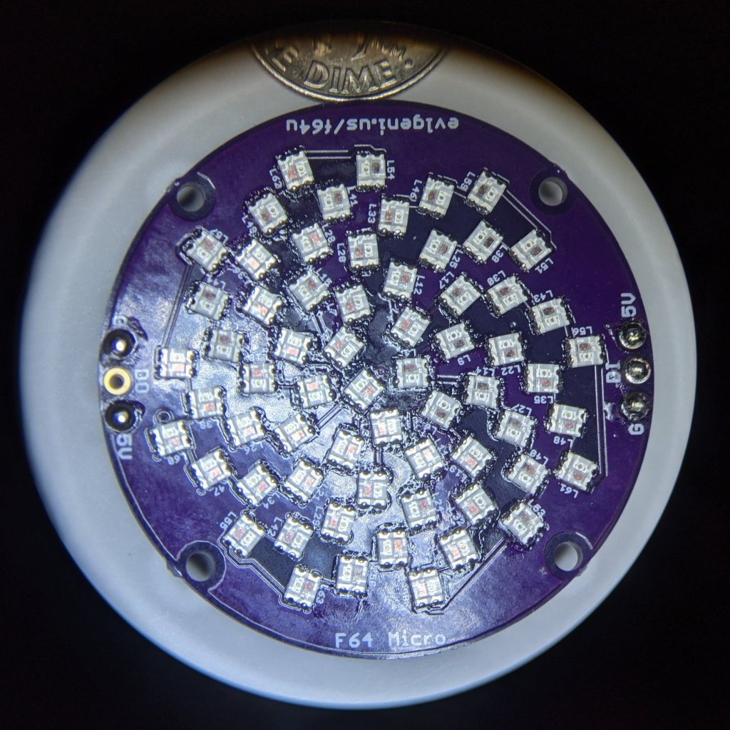
This new creation from Jason Coon packs 64 RGB LEDs on a 20 mm disc in a Fibonacci distribution:

I have created several LED art pieces in Fibonacci patterns. They are all very labor intensive to create, and so are fairly expensive and limited in quantity. I wanted to come up with a Fibonacci layout that was at least slightly easier to create, and therefore more affordable.

I have RGB LEDs in just about every form they come: strips, strings, rings, discs, etc. The LEDs on most discs are arranged in very regular rings. Fibonacci64 is different. The LEDs are arranged in a Fibonacci distribution. The makes the layout very organic and seemingly messy. But with the proper animation, spiral patterns emerge with spectacular results.

The WS2812C-2020 each only consume a maximum of 5mA, and that’s at 100% brightness, solid white color. That’s only 320 mA for all 64 combined. They are still very bright, and I usually only run them at about 25% brightness. They’re perfect for wearables, powered with LiPo batteries.

Read more…

Here is it in action:

Fibonacci64 Micro

Fibonacci512 giant LED disc

From Jason Coon of Evil Genius Labs:

Fibonacci512 is a giant, beautiful 320mm circular disc with 512 RGB LEDs surface mounted in a Fibonacci distribution. Swirling and pulsing like a colorful galaxy, it’s mesmerizing to watch.

It consists of 512 WS2812B-Mini 3535 RGB LEDs, arranged into a circular Fermat’s spiral pattern.

I have created several LED art pieces in Fibonacci patterns. They are all very labor intensive to create, and so are fairly expensive and limited in quantity. I wanted to come up with a Fibonacci layout that was at least slightly easier to create, and therefore more affordable.

I have RGB LEDs in just about every form they come: strips, strings, rings, discs, etc. The LEDs on most discs are arranged in very regular rings. Fibonacci512 is different. The LEDs are arranged in a Fibonacci distribution. The makes the layout very organic and seemingly messy. But with the proper animation, spiral patterns emerge with spectacular results.

Each of the 512 WS2812B-Mini 3535 RGB LEDs has its own decoupling capacitor built in. The top and bottom of the PCB are large 5V and GND planes, to allow for the large amount of current required by the 512 LEDs. The PCB is split into four separate data lines to allow for higher frame rates when driven by a microcontroller that supports the FastLED library’s parallel output, such as ESP8266, ESP32, Teensy, etc. The max theoretical frame rate with four way parallel output is ~260 FPS. Each of the four data lines has a separate four-pin headers provided for 5V, Data In (to the section), Data Out (from the previous section) and GND. The last Data Out pin can be used to connect to even more LEDs. There are also small jumper solder pads that can be bridged to drive the whole panel with a single pin (max ~65 FPS), or two pins (max 130 FPS).

Read more on Tindie…

Fibonacci512 giant LED disc

Ethernet-Powered Christmas Tree

Glen Atkins wrote a blog post about a recent project for the holidays:

It’s an Ethernet-Powered Christmas Tree!

The lighted tree in the video above gets both the power and data for its RGB LED pixels using a single Ethernet cable. Power for the pixels is supplied from an Ethernet switch using the 802.3at PoE+ standard. Data for the pixels comes from software running on a PC that generates Art-Net packets at 40 Hz. Each Art-Net packet contains the RGB levels for all the pixels on the tree. Let’s take a closer look at the technical details and how this tree came into existence.

EM-6khRU4AARNAr

A few weeks ago, I wrote a post where I reversed engineered some Philips Color Kinetics iColor Flex RGB LED string lights. These lights require an AC power data supply that supplies 24 volts to power the pixels and transforms DMX or UDP packets of pixel data into the protocol used by the pixels. In addition to the power supply, the pixels require a proprietary leader cable to connect them to the power supply.

IMG_20191207_120244-2000-1024x682

In a typical setup, you have to run AC mains power and Ethernet data to the power supply then run the leader cable to the pixels. To avoid having a large stack of power data supplies in larger setups, Color Kinetics makes a rack mount power supply that can power up to eight strings of lights. This rack mount power supply still requires a leader cable for each string of lights.

thumbnail-1024x576.jpg

I’ve been wanting to build an 802.3af/at/bt Power over Ethernet design for a few years now and have always come up short on ideas and then it hit me, what if the Ethernet cable could connect closer to the pixels in the photo above? With a small box of electronics between the Ethernet cable and the connector on the end of the pixels, the pixels could receive both power and data from the Ethernet switch. No more AC mains wiring and no more proprietary leader cables.


Ethernet-Powered Christmas Tree

TritiLED Flashes for 20 Years on a Single Coin Cell

From  on Tindie blog:

tritiled

TritiLED Flashes for 20 Years on a Single Coin Cell

Ted Yapo had a small problem. As an amateur atronomer and astrophotographer, he needed a way to mark his expensive equipment so that he wouldn’t trip over it in the dark. Glow-in-the-dark materials were out because of they only glow for a short time, and glow sticks were also less than ideal because of their single-use nature. Tritium light sources would be perfect, barring the small details that they’re radioactive, expensive, and in the US only a few uses are allowed, most are prohibited by law.

tritiled1

So Yapo instead came up with an LED light that can run for not 20 hours, or even 20 days, but 20 yearson a single CR2032 coin cell battery!

TritiLED Flashes for 20 Years on a Single Coin Cell

reDot Smart 5×7 LED Matrix

Alex on Hackaday.io is working on a smart miniature (DIP6) 5×7 LED Matrix:

5081641517597723580.JPG

reDOT_smart

This project is based on my #reDOT project. Basicly it is a 5×7 SMD LED Matrix an a microcontroller on one PCB. I started wirh 0201 LEDs (see first project log), but this was not reliable. So a second version with 0402 is in development. 0402 LEDs do have some benefits over 0201:

  • bigger and you can solder them better
  • cheaper
  • more colors availible

The microcontroller (a low coast STM8) drives all LEDs directly with multiplexing. For controlling a UART interface is available. The dimensions are like a DIP-6 package. For easy connection of multiple PCBs, the pads are castellated. Also the supply rails are available on both sides. So multiple of these display can be soldered together to a bigger display without the need of additional wiring.

reDot Smart 5×7 LED Matrix

LED ring

Jens Hauke designed this charlieplexed 20 LED blinker controlled by an ATTiny45 for the Hackaday Coin Cell Challenge:

156251514462780263

LED Ring

This is a small blinky with 20 LEDs powered by one CR2032 coin cell
and with an ATTiny45 brain. The firmware is written in plain C and
compiled with the avr-gcc toolchain. The PCB is a two layer design made
with KiCad.
Space efficient daisychained LED placing with shared anode/cathode soldering pads.

Firmware and gerbers are available on GitHub:

jensh/attiny-20led-ring


Jens has shared the board on OSH Park:

LED 20 Ring ATTiny

65a7204f0dcd3a7d1b3f36c7370cb7af

Order from OSH Park

Here is a video of the LED in action:

LED ring

Snowbot

A holiday project by Dan Hienzsch (@rheingoldheavy) to build a little Snowbot with an adjustable speed larson scanner for an eye:

2999791454992848983.jpg

Snowbot V1.0

The Snowbot has three major subsystems: Power and Timer and Display.

Power Subsystem

The power subsystem uses a 3.7V LiPO battery boosted to 5V with an SC4503 boost converter to power the fully analog circuit. It requires a set of passive components in order to generate the higher voltage.

3145851454992895613.jpg

Timer Subsystem

The timer subsystem is comprised of a 555 IC that generates a clock signal. The speed of the clock is adjusted by twisting the potentiometer (the nose of the snowbot). The clock signal ticks through the outputs of a CD4017 decade counter, lighting each LED in sequence, then moving back through them again.

8990681454993097528

Display Subsystem

The display subsystem involves taking the output of the CD4017, and directing it to six red LEDs in the form of a larson scanner. In addition to lighting the LED, the current also charges a 22uF capacitor through a diode. When the output moves to the next LED, the cap discharges through a 2.2K resistor (part of a resistor network), fading the LED out gracefully.

Snowbot

How Fast is Your Fidget Spinner?

From Ken Olsen of The Maker’s Box:

How Fast is Your Fidget Spinner?

You never know what people will do with your ideas, and it is always fun to see someone do something I would have never thought off with them.  I got a video from someone who built my Programmable Fidget Spinner, and used a leaf blower to see how fast they could get it to go.  Fortunately, they were wearing safety glasses, and no, it didn’t come flying apart.  It did, however, start displaying erratically at about 3600 RPM (the fastest I can get it by hand is just under 2000 RPM).

So, what is going on?  TLDR: I figured it out and fixed it, and here is proof.

How Fast is Your Fidget Spinner?

Maker Faire Orlando soldering kit

MFO-SK7-03-Assembled-F-1080x550

We are proud to be a sponsor of this Maker Faire Orlando soldering kit:

Advanced soldering training at Maker Faire Orlando

For the past six years at Maker Faire Orlando, members of FamiLab have taught attendees how to solder with a cool little Makey pin with 2 self-flashing LEDs.  We’ve been asked for more advanced soldering training, and we responded with the addition of a PIC-microcontroller-based board twinkling several LEDs, and with a switch that can be used to change the LED display pattern.

We opted to design the board such that it can be used as a pendant on a necklace (lanyard) or as a keychain (especially for those of you who like large keychains). The design is a scalloped 2.7″ circle with LEDs on the outside circle, and a hole at the top for a keyring. Batteries are on the back of the board.

Resources

Maker Faire Orlando soldering kit