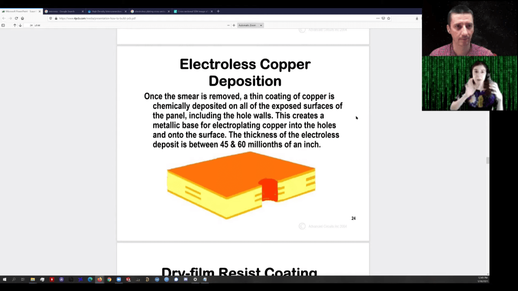
Fascinating walk through of PCB fabrication in this video from Robert Feranec featuring Kailey Shara who discussed research into DIY PCB through-hole plating:
Do you know why PCB Manufacturer may use tin to protect tracks and VIAs when your PCB is manufactured? Do you know how exactly PCB VIA plating is done? Thank you Kailey Shara for explanation
In 2018, when KiCad Version 5 modernized the venerable 4.X series, it helped push KiCad to become the stable and productive member of the open source EDA landscape that we know today. It has supported users through board designs both simple and complex, and like a tool whose handle is worn into a perfect grip, it has become familiar and comfortable. For those KiCad users that don’t live on the bleeding edge with nightly builds it may not be obvious that the time of version 6 is nearly upon us, but as we start 2021 it rapidly approaches. Earlier this month [Peter Dalmaris] published a preview of the changes coming version 6 and we have to admit, this is shaping up to be a very substantial release.
Don’t be mistaken, this blog post may be a preview of new KiCad features but the post itself is extensive in its coverage. We haven’t spent time playing with this release yet so we can’t vouch for completeness, but with a printed length of nearly 100 pages it’s hard to imagine [Peter] left anything out! We skimmed through the post to extract a few choice morsels for reproduction here, but obviously take a look at the source if you’re as excited as we are.
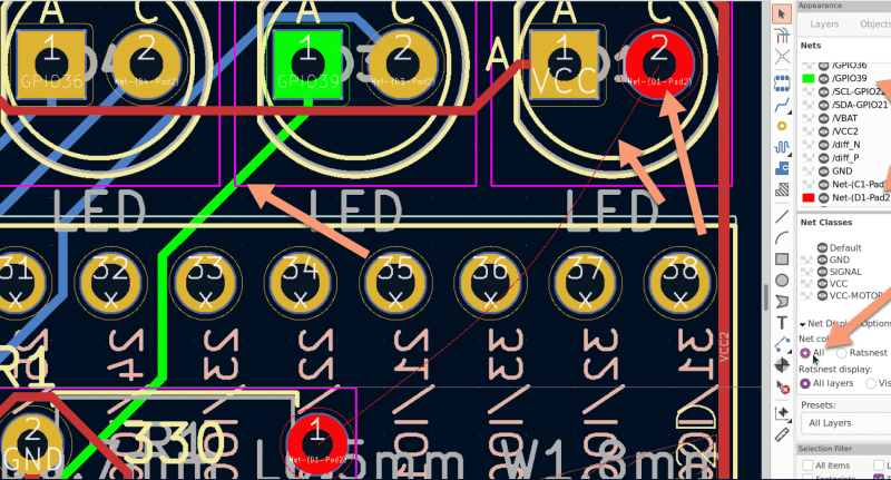
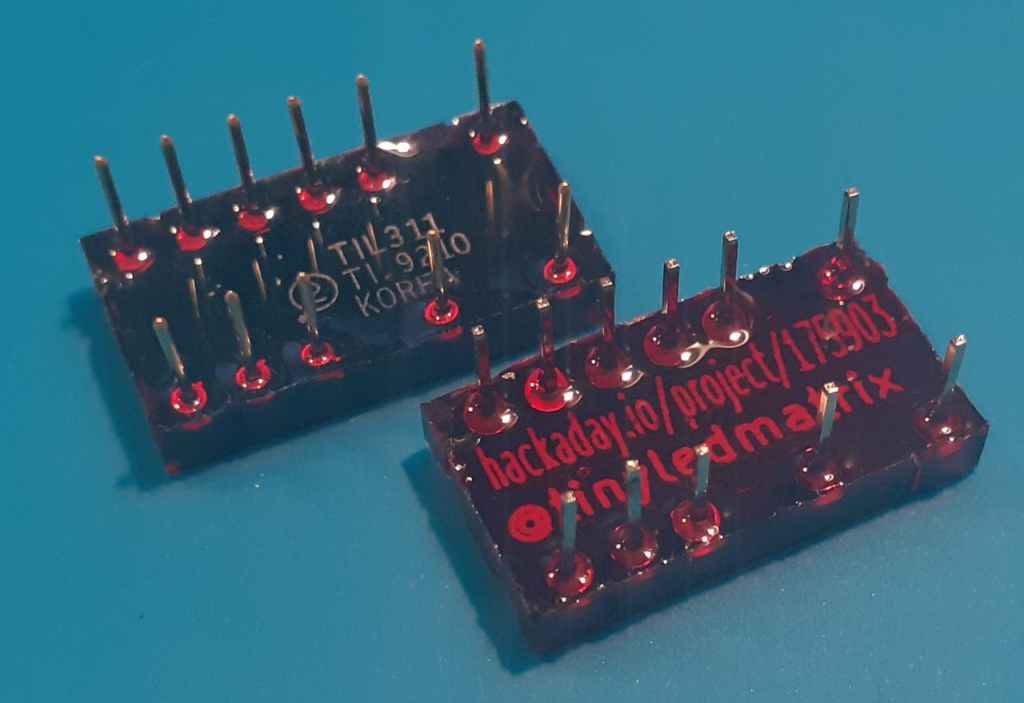
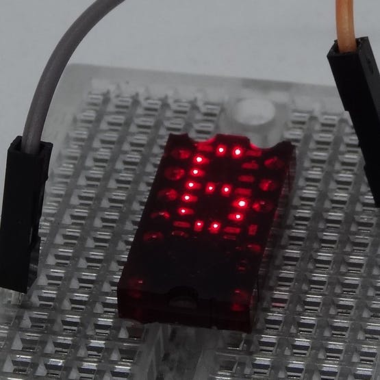
Tom Fleet writes on Hackster about the reTIL from Alex (@tinyledmatrix): reimagined, resin-cast, retro-tech style programmable TIL311 LED hexadecimal display replacement:
Packing the tiny array of individual single LED pixels into place, along with a super-smol STM8S QFN MCU, all on the front face of the PCB, leaves a layout that is almost indistinguishable from the TIL311 when illuminated.
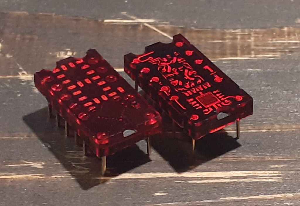
But, @tinyledmatrix didn’t stop there, oh no. Striving for a true-to-form-factor facsimile, the re-vamped PICTIL is placed into a mold, before being cast in the same tinted resin — and the results are just stunning. Below, we can see the fruits of the labour, with the new, modern take shown on the left, and the original TIL311 to the right
Installed in a product, you’d be hard pushed to tell the difference once the LEDs are lit up!
You can do your own Surface Mount Technology based PCB assembly with just a handful of tools and some patience. At the heart of my SMT process is stopping to inspect the various steps all while trying to maintain a bit of cleanliness in the process.
Surface mount or Surface Mount Technology (SMT) is the modern way to assemble Printed Circuit Boards (PCB) and is what is commonly seen when opening a modern piece of tech. It’s much smaller than the older Through-Hole (TH) technology where the component leads were inserted into holes in PCB, and act we called “stuffing” since we had to stuff the components into the holes.
A few specialized tools make this a lot easier, but resourceful hackers will be able to pull together a solder paste stencil jig, vacuum tweezers, and a modified toaster oven with a controller that can follow the reflow profile of the solder paste. Where you shouldn’t skimp is on the quality, age, and storage of the solder paste itself.
Join me after the break for my video overview of the process I use in my workshop, along with details of every step of my SMT assembly process.
The Goodbye 2020 contest asked you to turn out the lights on an objectively crappy year in an interesting way. Four winners have been announced, and we have to tip the hat to [Becky Stern] for both creativity and execution on the 2020 candle seen above. Three wicks burn the candle down, revealing a metalwork dumpster fire along the way. It’s not just a performance piece but also an interesting look into candle making with 3D printed molds and insight on specifics like pour-temperature for best results. [Becky] entered as a group with a few other YouTube channels that included gags like [TechnoChic’s] knitted 2020 mask that is unraveled to count down the to the end.
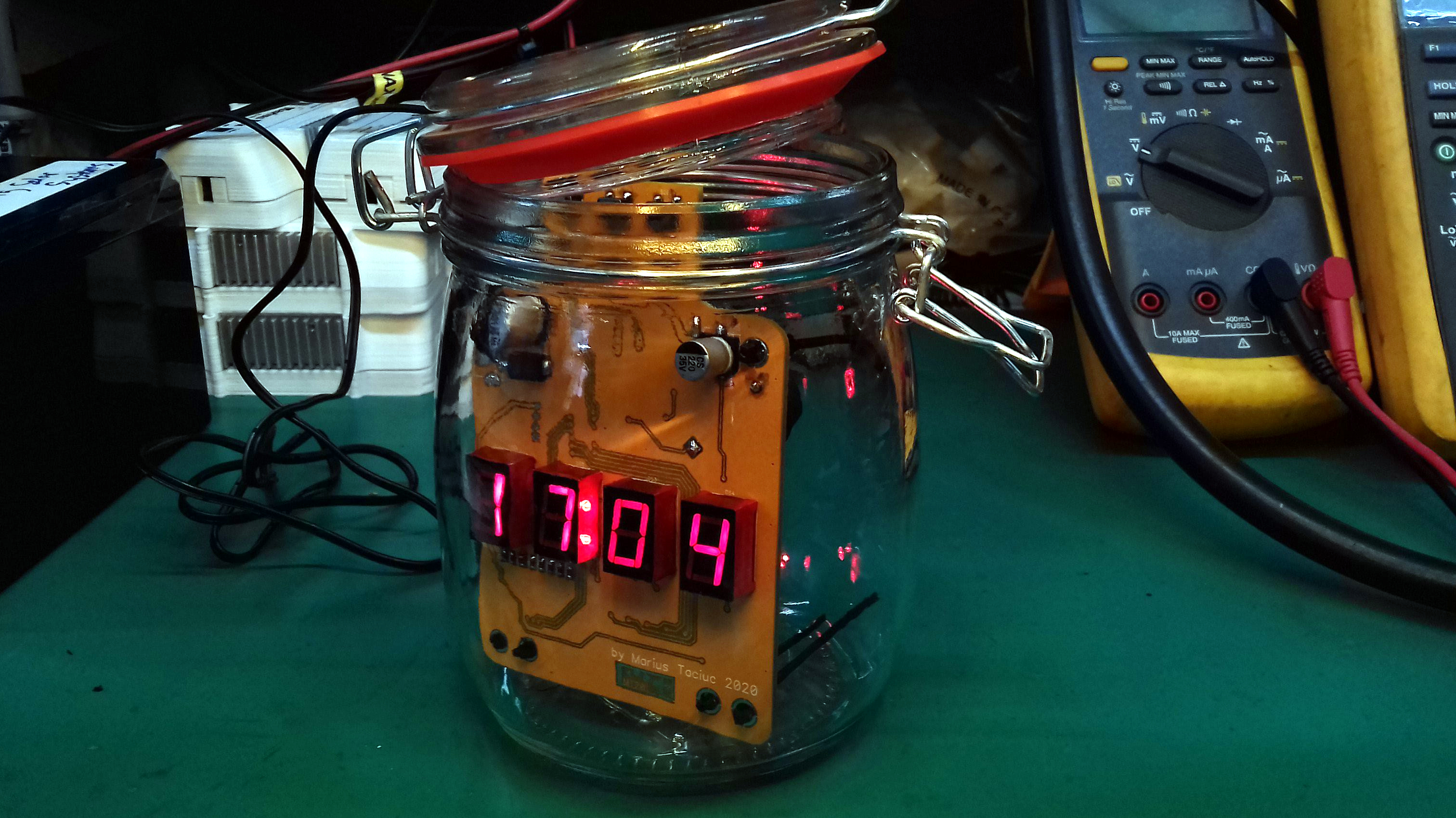
[Marius Taciuc] spun up a clock to count down his year. The custom PCB uses a set of 7-segment displays to show the time (and some custom messages), along with a battery-backed RTC for precision. The aesthetic is a PC overclocker’s dream as the timepiece lives inside of a mason jar filled with baby oil.
You certainly can’t go out to a rave during these pandemic times. [George Cave] brought the party to his face with a set of shades that blast RGB light into your eyeballs. A pair of ultasonic distance sensors shut the party down if anyone breaks social distancing guidelines.
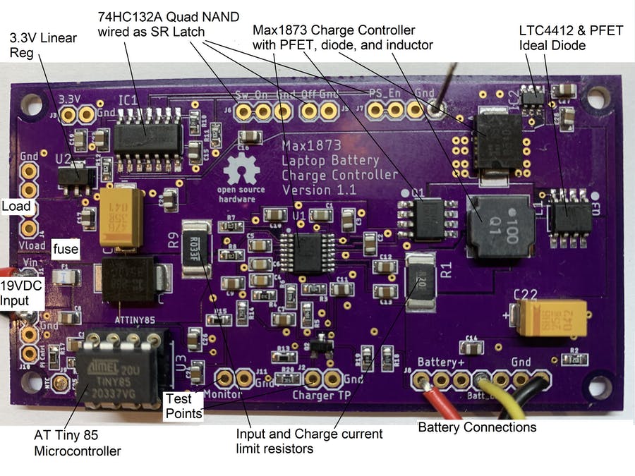
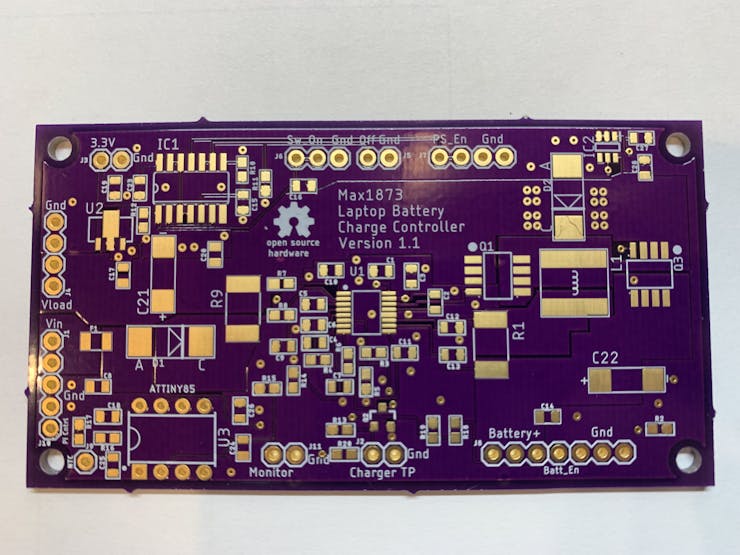
his project is for those that want to turn an old laptop into a portable Raspberry Pi. My previous Hackster.io projects showed how to connect the keyboard and touchpad. The LCD is easy to convert to HDMI with a video card from EBay. The missing piece has been a way to charge the original lithium battery pack. To solve this problem, I designed a circuit board in Eagle that uses a Max1873 charge controller with an ATtiny85 as a supervisor. The board shown below was fabricated by OSH Park. The Eagle board and schematic files plus the ATtiny code can be downloaded below.
The Max1873 has been around a long time and needs a microcontroller to handle the tasks that a newer charger IC would have, built in. I have prior experience with this chip and found it to be fairly simple and easy to get working. The schematic below shows how the ATtiny85 is powered from the 5.4 volt regulator in the Max1873. This means the ATtiny is only operating if the wall supply is plugged in. The ATtiny outputs a logic signal that turns on an NFET which in turn disables the Max1873. This 5.4 volt logic signal is attenuated to a 3.3 volt level so it can be monitored by the Pi. If the ATtiny is not installed in it’s socket, the Max1873 will be enabled. The Pi could drive the “Charger_TP” signal to disable the charger if the battery values read over the SMBus show it’s necessary.
Now that it is relatively cheap and easy to create a PCB, it is a common occurrence for them to be used in projects. However, there are a lot of subtleties to creating high-performance boards that don’t show up so much on your 555 LED blinker. [Robert Feranec] is well-versed in board layout and he recently highlighted an animation on signal crosstalk with [Eric Bogatin] from Teledyne LeCroy. If you want a good understanding of crosstalk and how to combat it, you’ll want to see [Eric’s] presentation in the video below.
Simplifying matters, the heart of the problem lies in running traces close together so that the magnetic fields from one intersect the other. The math is hairy, but [Eric] talks about simple ways to model the system which may not be exact, but will be close enough for practical designs.
The models use inductors and capacitance to represent different modes of crosstalk, and it’s likely you already know how to deal with those quantities. The video shows some simulations and also suggests methods to control the problem.
Even though the topic is PC boards, some of the same ideas apply to cables. Ethernet cables, for example, have specifications for FEXT for similar reasons.
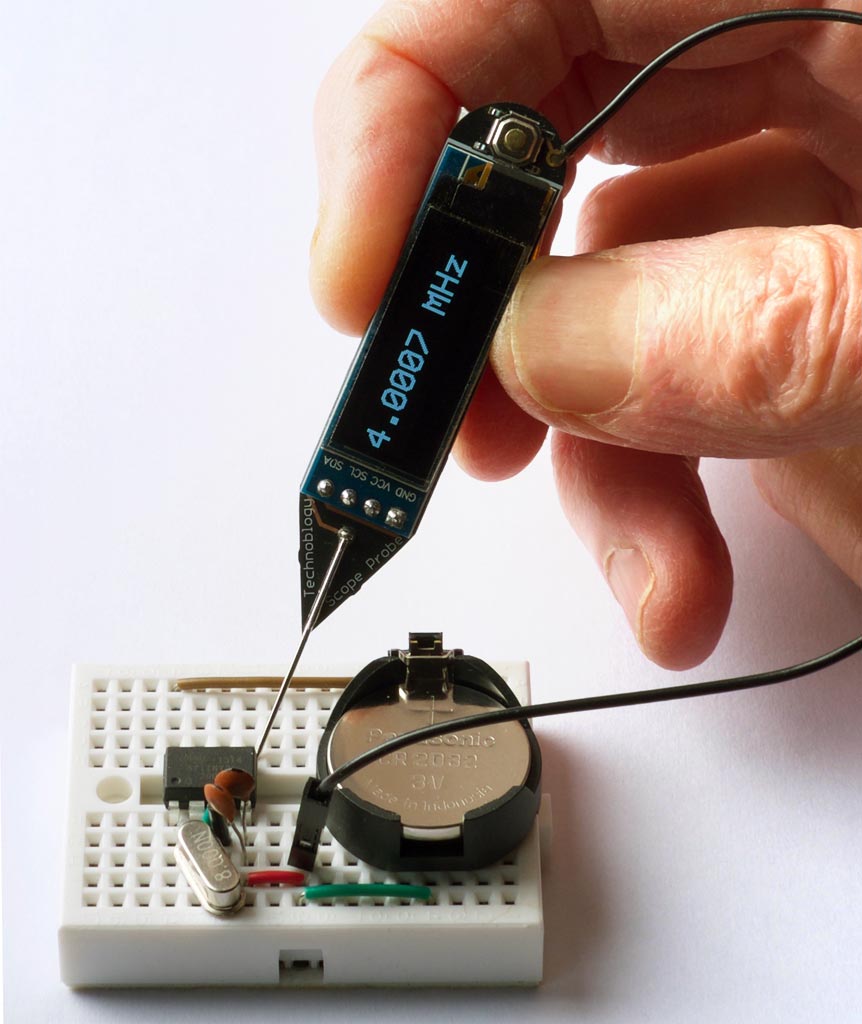
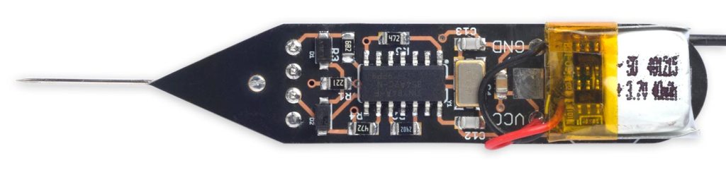
The Frequency Probe is a handheld tool designed to help you debug your circuits by giving a visual indication of the frequency or voltage at the probe. For a periodic waveform it gives a digital readout of the frequency, with a range of about 1Hz to 5MHz and an accuracy of better than 0.3%. For a voltage level it gives a readout of the voltage:
The obvious way to implement a frequency meter is to count the number of pulses within one second; this then directly gives the frequency. I refer to this as Frequency Mode. The disadvantage of this method is that a long sample time is needed to measure low frequencies accurately.
The other way is to measure the interval between two pulses of the input signal; the reciprocal of this then gives the frequency. I call this Interval Mode. For example, if the interval between pulses is one second the frequency is 1Hz. The disadvantage of this method is that for high frequencies you need to measure the interval very accurately.
The ideal solution is to use Frequency Mode for high frequencies, and Interval Mode for low frequencies, which is the approach I’ve adopted with the Frequency Probe. I explain below how to calculate the best point at which to switch between modes.
I originally started work on this project a couple of years ago, but it turned out to be a lot trickier than I anticipated, and so decided to put it to one side. I revisited it earlier this year, and fortunately managed to solve all the issues.
The US is primed and ready for open source hardware to accelerate scientific breakthroughs, but open source hardware needs a cemented place on the intellectual property landscape within the sciences enabling a faster, more efficient acceleration. If we can cement science using open source hardware, we’ve got a path to expanding American manufacturing. Many businesses profit from open source hardware, demonstrating that it is a lucrative business model. The field of science needs equipment for all sorts of experiments and lab work. Let’s apply the groundwork already laid in the United States for open source hardware to be the default for science.