LED ring

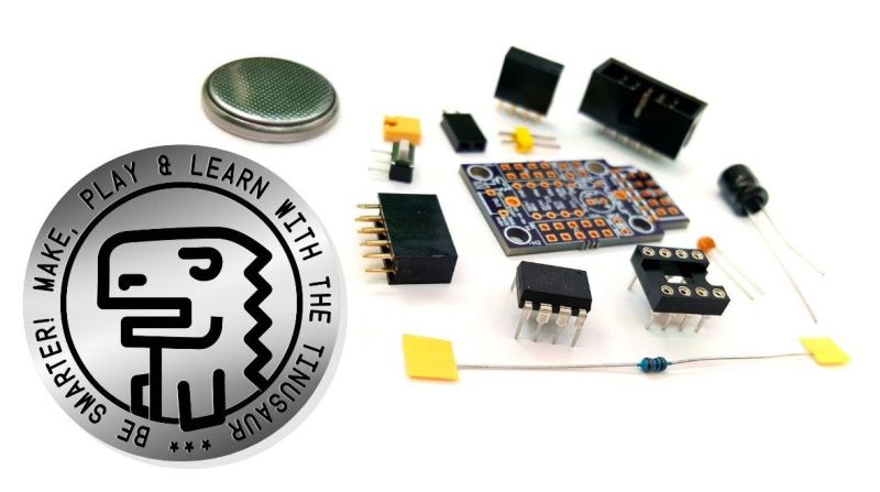
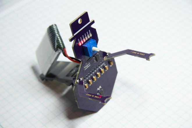
Jens Hauke designed this charlieplexed 20 LED blinker controlled by an ATTiny45 for the Hackaday Coin Cell Challenge:
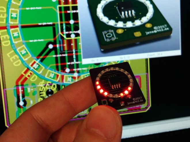
156251514462780263

LED Ring

This is a small blinky with 20 LEDs powered by one CR2032 coin cell
and with an ATTiny45 brain. The firmware is written in plain C and
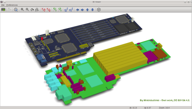
compiled with the avr-gcc toolchain. The PCB is a two layer design made
with KiCad.
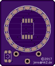
Space efficient daisychained LED placing with shared anode/cathode soldering pads.

Firmware and gerbers are available on GitHub:

jensh/attiny-20led-ring


Jens has shared the board on OSH Park:

LED 20 Ring ATTiny

65a7204f0dcd3a7d1b3f36c7370cb7af

Order from OSH Park

Here is a video of the LED in action:

LED ring

There Once Was an IC Dedicated to Blinking an LED

https://youtube.com/watch?v=TYnx2c-3YMM%3Fversion%3D3%26rel%3D1%26fs%3D1%26autohide%3D2%26showsearch%3D0%26showinfo%3D1%26iv_load_policy%3D1%26wmode%3Dtransparent

Today you can buy flashing LEDs; a simple two-lead component that requires only a power supply to produce even flashes of light. They look for all the world like any other LED, though embedded in the plastic dome is an integrated circuit to do all that flashing work. There was a time though when a…

via There Once Was an IC Dedicated to Blinking an LED — Hackaday

There Once Was an IC Dedicated to Blinking an LED

HDDG 26: Amateur Radio and Robot Overlords

highres_467291927.jpeg

The next Hardware Developers Didactic Galactic is on Thursday, January 11th, at SupplyFrame’s San Francisco office:


https://www.meetup.com/Hardware-Developers-Didactic-Galactic/events/246401401/

The presenters will be:

HDDG 26: Amateur Radio and Robot Overlords

State of KiCad this Friday

kicadhackchat-01.png
Wayne Stambaugh from the KiCad project be joining Hack Chat on Hackaday.io this Friday to discuss upcoming plans and features for 2018:

kicad2

The State of KiCad

Friday, January 5, 2018 12:00 pm PST

  • What new features are on the roadmap for 2018?
  • What new features were developed since we chatted in January 2017?
  • Under the hood- how KiCad development works
  • How can a developer get started helping out?

Screenshot from 2018-01-02 23-27-04.png

State of KiCad this Friday

Short Video about the Tinusaur Project


This is a short 2-minute video explaining what is the Tinusaur project about, who is it good for and what you could do with its microcontroller and shield boards. The Tinusaur is a small microcontroller board with a tiny chip on it. The Tinusaur board is powered by the popular Atmel ATtiny85 microcontroller. It comes as […]

via Short Video about the Tinusaur Project — The Tinusaur Project

Short Video about the Tinusaur Project

Black Mesa Labs: DVI digital video for FPGAs over PMOD

2017.12.15 : Black Mesa Labs is proud to present two open-source-hardware DVI video boards for adding TMDS digital video to FPGA platforms with standard PMOD connectors. These two boards are currently available to purchase as bare fabs directly from OSH-Park, or Gerbers and design files may be downloaded from BML here. ——————————————————– BML 3bit DVI […]

via BML DVI digital video for FPGAs over PMOD — Black Mesa Labs

Black Mesa Labs: DVI digital video for FPGAs over PMOD

Exporting Eagle Libraries to FOSS Tools

Since Autodesk’s acquisition, Eagle has been making waves in the community. The de facto standard for Open Hardware PCB design is now getting push-and-shove routing, a button that flips the board over to the back (genius!), integration with Fusion360, automated 3D renderings of components, and a bunch of other neat tools. However, Eagle is not without its…

via Exporting Eagle Libraries to FOSS Tools — Hackaday

Exporting Eagle Libraries to FOSS Tools

Coin Cell Challenge: Jump Starting a Car

Clearly a believer in the old adage, “Go Big or Go Home”, [Ted Yapo] has decided to do something that seems impossible at first glance: starting his car with a CR2477 battery. He’s done the math and it looks promising, though it’s yet to be seen if the real world will be as accommodating. At the…

via Coin Cell Challenge: Jump Starting a Car — Hackaday

Coin Cell Challenge: Jump Starting a Car

Snowbot

A holiday project by Dan Hienzsch (@rheingoldheavy) to build a little Snowbot with an adjustable speed larson scanner for an eye:

2999791454992848983.jpg

Snowbot V1.0

The Snowbot has three major subsystems: Power and Timer and Display.

Power Subsystem

The power subsystem uses a 3.7V LiPO battery boosted to 5V with an SC4503 boost converter to power the fully analog circuit. It requires a set of passive components in order to generate the higher voltage.

3145851454992895613.jpg

Timer Subsystem

The timer subsystem is comprised of a 555 IC that generates a clock signal. The speed of the clock is adjusted by twisting the potentiometer (the nose of the snowbot). The clock signal ticks through the outputs of a CD4017 decade counter, lighting each LED in sequence, then moving back through them again.

8990681454993097528

Display Subsystem

The display subsystem involves taking the output of the CD4017, and directing it to six red LEDs in the form of a larson scanner. In addition to lighting the LED, the current also charges a 22uF capacitor through a diode. When the output moves to the next LED, the cap discharges through a 2.2K resistor (part of a resistor network), fading the LED out gracefully.

Snowbot