Snowbot

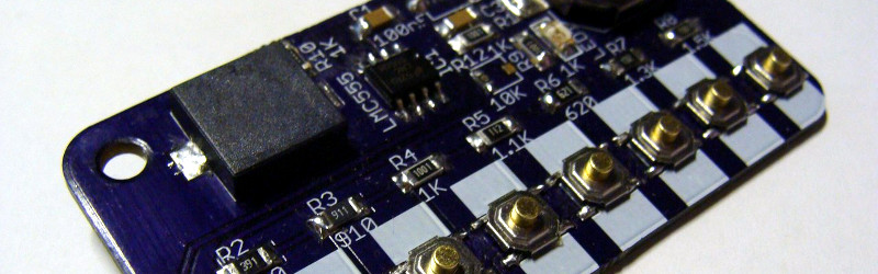
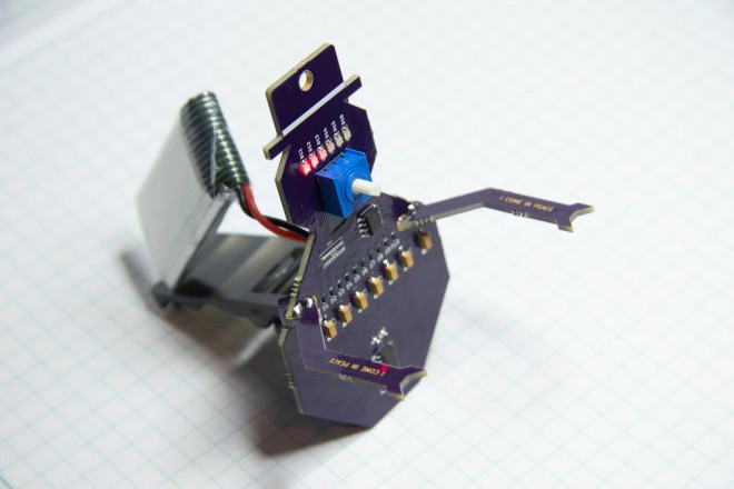
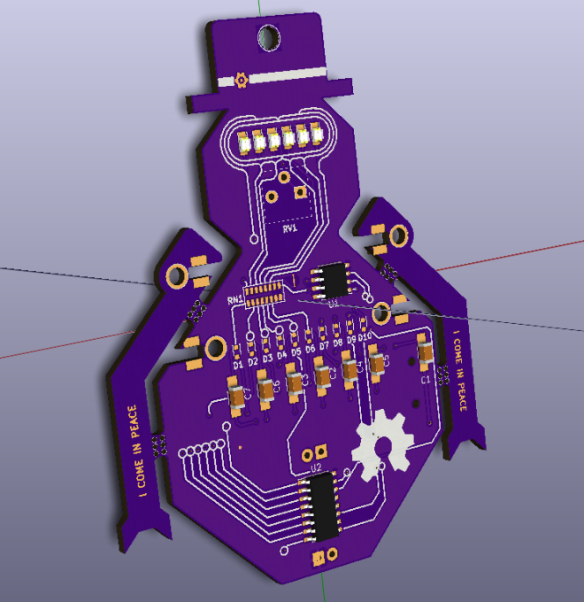
A holiday project by Dan Hienzsch (@rheingoldheavy) to build a little Snowbot with an adjustable speed larson scanner for an eye:
2999791454992848983.jpg

Snowbot V1.0

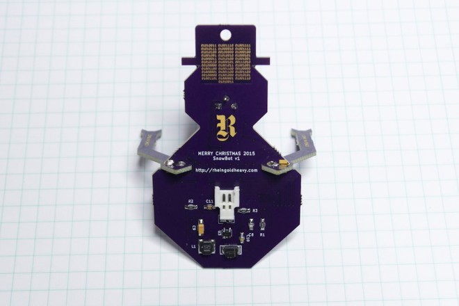
The Snowbot has three major subsystems: Power and Timer and Display.

Power Subsystem

The power subsystem uses a 3.7V LiPO battery boosted to 5V with an SC4503 boost converter to power the fully analog circuit. It requires a set of passive components in order to generate the higher voltage.
3145851454992895613.jpg

Timer Subsystem

The timer subsystem is comprised of a 555 IC that generates a clock signal. The speed of the clock is adjusted by twisting the potentiometer (the nose of the snowbot). The clock signal ticks through the outputs of a CD4017 decade counter, lighting each LED in sequence, then moving back through them again.
8990681454993097528

Display Subsystem

The display subsystem involves taking the output of the CD4017, and directing it to six red LEDs in the form of a larson scanner. In addition to lighting the LED, the current also charges a 22uF capacitor through a diode. When the output moves to the next LED, the cap discharges through a 2.2K resistor (part of a resistor network), fading the LED out gracefully.

Snowbot

Sarah Petkus On Building A Cartoon To Go To Mars

Sarah Petkus is a robot mom (which means she’s the mother to a robot, not that Sarah herself is a robot, at least as far as we’re aware), whose child, Noodle Feet, is a character in Sarah’s graphic novel Gravity Road. Unlike every other robot on the planet, Noodle Feet is a content-based robot. Instead of…

via Sarah Petkus On Building A Cartoon To Go To Mars — Hackaday

Sarah Petkus On Building A Cartoon To Go To Mars

Rapid Surface Mount Prototyping

2017.12.03 0.100″ proto boards are readily available and great for prototyping with 1980’s DIP thru-hole technology. Trying to use them with 1990s and newer surface mount devices is like picking your teeth with a log however. 0.050″ pitch vias line up perfectly with SOIC ICs, SOT-23s and 0603s passives but for whatever reason proto boards […]

via BML 50mil (0.050″ , 1.27mm) Proto Boards for Rapid Surface Mount Prototyping — Black Mesa Labs

Rapid Surface Mount Prototyping

USB 3.0 FPGA interface over PMOD

2017.12.19 : Black Mesa Labs is presenting an open-source-hardware USB 3.0 to FPGA PMOD interface design. First off, please lower your expectations. USB 3.0 physical layer is capable of 5 Gbps, or 640 MBytes/Sec. This project can’t provide that to your FPGA over 2 PMOD connectors – not even close. It does substantially improve PC […]

via BML USB 3.0 FPGA interface over PMOD — Black Mesa Labs

USB 3.0 FPGA interface over PMOD

1bitsy and Black Magic Probe

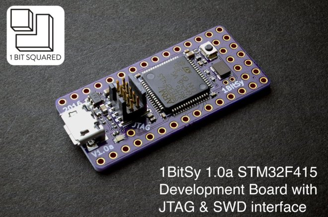
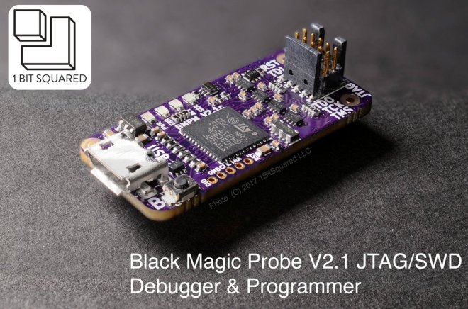
The 1bitsy and Black Magic Probe are now available in our store:

1bitsy_v1_0a_legend_1024x1024

1Bitsy STM32F415 Development Board

Open-Source Miniature Breadboard Friendly ARM Cortex-M4F Dev Board with 1MB Flash, 196kB RAM, 168MHz, floating point and more.

bmpm_v2_1c_purple_top_1024x1024

Black Magic Probe V2.1

Plug and Play JTAG/SWD USB programmer and debugger with a built in GDB server and TTL level UART to USB adapter.


1bitsy and Black Magic Probe

DIY Gaming Handheld Powered by C.H.I.P.

From the Next Thing Co blog:

Community Made: Groboy is a DIY Gaming Handheld Powered by C.H.I.P. Pro

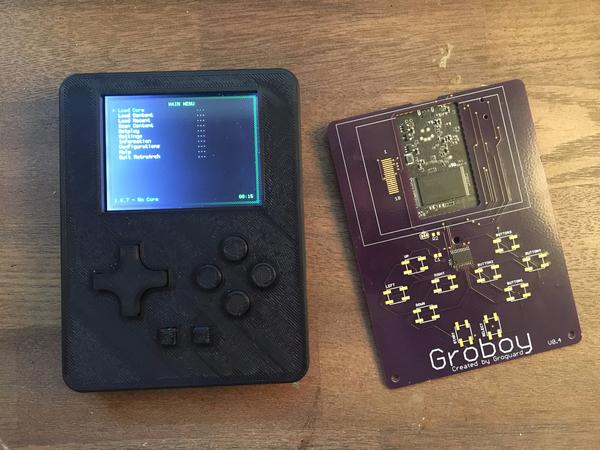
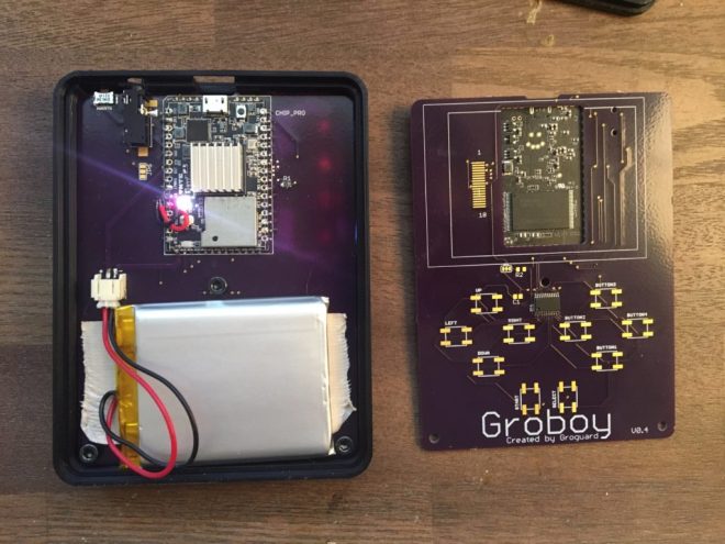
Groboy, created by Groguard, is a C.H.I.P. Pro-powered handheld system designed to run retro console emulators and games on the go.

herogroboy

It’s also a testament to the open source community, readily available data sheets and manufacturing houses, and the tenacity to teach yourself engineering. Groguard, like many of us, is self-taught and pursuing his passion for making through custom projects.

groboyback-1024x768.jpg

After 4 revisions of the board, Groguard had the design where he wanted it. The custom OSH Park PCB at the heart of Groboy routes signal lines from the 2.8″ TFT display, headphones jack, internal 2500mAh LiPo battery (he estimates 3-5 hours of battery life, though he’s not rigorously tested it), and the PCA9555 I2C GPIO expander, which manages inputs from the 11 onboard buttons, to the respective input and output pins on C.H.I.P. Pro.

DIY Gaming Handheld Powered by C.H.I.P.

Rotary Encoder with I2C Interface and RGB Lighting

From on the Tindie blog:

encoder

Rotary Encoder with I2C Interface and RGB Lighting

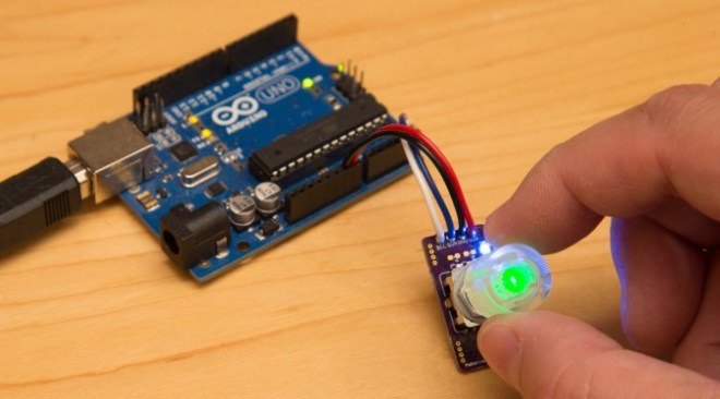
Makernet Knob’s makes the point that “Rotary encoders are cool but hard to wire into your projects.” Having wired up a custom input device for my computer using an encoder, I can attest to both of these statements. In my case, it took me quite a bit of time simply to figure out how each encoder pin was used!


Rotary Encoder with I2C Interface and RGB Lighting

How Fast is Your Fidget Spinner?

From Ken Olsen of The Maker’s Box:

How Fast is Your Fidget Spinner?

You never know what people will do with your ideas, and it is always fun to see someone do something I would have never thought off with them.  I got a video from someone who built my Programmable Fidget Spinner, and used a leaf blower to see how fast they could get it to go.  Fortunately, they were wearing safety glasses, and no, it didn’t come flying apart.  It did, however, start displaying erratically at about 3600 RPM (the fastest I can get it by hand is just under 2000 RPM).

So, what is going on?  TLDR: I figured it out and fixed it, and here is proof.

How Fast is Your Fidget Spinner?