Debugging PCBs with Augmented Reality

Screenshot from 2020-03-10 11-51-32

The idea of InspectAR is to use augmented reality to help work with and debug electronics. It’s a powerful suite of tools that enable the live overlay of graphics on a video feed of a circuit board, enabling the user to quickly and effectively trace signals, identify components, and get an idea of what’s what. Usable with a smartphone or a webcam, the aim is to improve collaboration and communication between engineers by giving everyone a tool that can easily show them what’s going on, without requiring everyone involved to run a fully-fledged and expensive electronics design package.

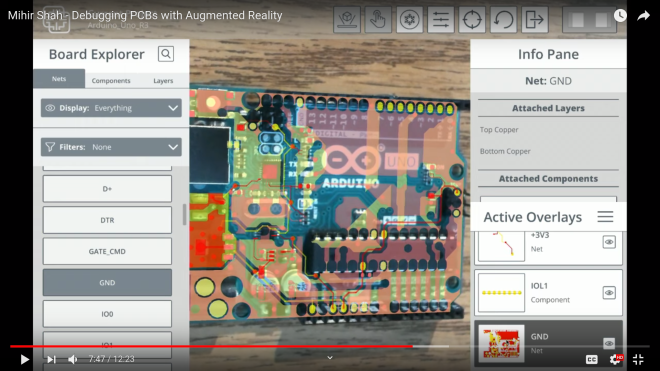
The Supercon talk served to demonstrate some of the capabilities of InspectAR with an Arduino Uno. With a few clicks, different pins and signals can be highlighted on the board as Mihir twirls it between his fingers. Using ground as an example, Mihir first highlights the entire signal. This looks a little messy, with the large ground plane making it difficult to see exactly what’s going on. Using an example of needing a point to attach to for an oscilloscope probe, [Mihir] instead switches to pad-only mode, clearly revealing places where the user can find the signal on bare pads on the PCB. This kind of attention to detail shows the strong usability ethos behind the development of InspectAR, and we can already imagine finding it invaluable when working with unfamiliar boards. There’s also the possibility to highlight different components and display metadata — which should make finding assembly errors a cinch. It could also be useful for quickly bringing up datasheets on relevant chips where necessary.

via Debugging PCBs with Augmented Reality — Hackaday

Quote

Scott Shawcroft Is Programming Game Boys With CircuitPython

Some people like to do things the hard way. Maybe they drive a manual transmission, or they bust out the wire wrap tool instead of a soldering iron, or they code in assembly to stay close to the machine. Doing things the hard way certainly has its merits, and we are not here to argue about that. Scott Shawcroft — project lead for CircuitPython — on the other hand, makes a great case for doing things the easy way in his talk at the 2019 Hackaday Superconference.

In fact, he proved how easy it is right off the bat. There he stood at the podium, presenting in front of a room full of people, poised at an unfamiliar laptop with only the stock text editor. Yet with a single keystroke and a file save operation, Scott was able make the LEDs on his Adafruit Edge Badge — one of the other pieces of hackable hardware in the Supercon swag bag — go from off to battery-draining bright.

via Scott Shawcroft Is Programming Game Boys With CircuitPython — Hackaday

Quote

Watch Linux Boot On Your Hackaday Superconference Badge

Last year’s Hackaday Superconference badge was an electronic tour de force, packing an ECP5 FPGA shoehorned into a Game Boy-like form factor and shipping with a RISC-V core installed that together gave an almost infinite badge hacking potential. It did not however run Linux, and that’s something [Greg Davill] has addressed, as he’s not only running Linux on his badge, but also a framebuffer that allows him to use the badge screen as the Linux terminal screen. Finally you can watch Linux boot on your Superconference badge itself, rather than over its serial port.

He’s achieved this by changing essentially everything: from the new VexRiscv CPU core, to new video drivers and a VGA terminal courtesy of Frank Buss, now part of the LiteVideo project. It’s not quite a fully fledged Linux powerhouse yet, but you can find it in a GitHub repository should you have a mind to try it yourself. Paging back through his Twitter feed reveals the effort he’s put into this work over the last few months, and shows that it’s been no easy task.

For those keeping score at home, this is an open hardware design, running an open CPU core, with community-designed open-source peripherals, compiled by an open-source toolchain, running an open-source operating system. And it’s simply a fantastic demo for the badge, showing off how flexible the entire system is. One of the best parts of writing for Hackaday is that our community is capable of a huge breadth of amazing pieces of work, and this is an exemplar of that energy. We can’t wait to see what Greg and any other readers tempted to try it will come up with.

If you’d like to refresh your memory over the 2019 Supercon badge, here’s our write-up at the time.

via Watch Linux Boot On Your Hackaday Superconference Badge — Hackaday

Quote

Open Laptop Soon to be Open For Business

How better to work on Open Source projects than to use a Libre computing device? But that’s a hard goal to accomplish. If you’re using a desktop computer, Libre software is easily achievable, though keeping your entire software stack free of closed source binary blobs might require a little extra work. But if you want a laptop, your options are few indeed. Lucky for us, there may be another device in the mix soon, because [Lukas Hartmann] has just about finalized the MNT Reform.

Since we started eagerly watching the Reform a couple years ago the hardware world has kept turning, and the Reform has improved accordingly. The i.MX6 series CPU is looking a little peaky now that it’s approaching end of life, and the device has switched to a considerably more capable – but no less free – i.MX8M paired with 4 GB of DDR4 on a SODIMM-shaped System-On-Module. This particular SOM is notable because the manufacturer freely provides the module schematics, making it easy to upgrade or replace in the future. The screen has been bumped up to a 12.5″ 1080p panel and steps have been taken to make sure it can be driven without blobs in the graphics pipeline.

via Open Laptop Soon to be Open For Business — Hackaday

Quote

The Newbie’s Guide To JTAG

This JTAG primer will get you up to snuff on snarfing, and help you build your reverse engineering skills.

Whatever your motivation for diving into reverse engineering devices with microcontrollers, JTAG skills are a must, and [Sergio Prado]’s guide will get you going. He starts with a description and brief history of the Joint Test Action Group interface, from its humble beginnings as a PCB testing standard to the de facto standard for testing, debugging, and flashing firmware onto devices. He covers how to locate the JTAG pads – even when they’ve been purposely obfuscated – including the use of brute-force tools like the JTAGulator. Once you’ve got a connection, his tutorial helps you find the firmware in flash memory and snarf it up to a file for inspection, modification, or whatever else you have planned.

via The Newbie’s Guide To JTAG — Hackaday

Quote

Software Defined Everything with Mike Ossmann and Kate Temkin


Software defined radio has become a staple of the RF tinkerer, but it’s likely that very few of us have ever taken their software defined toolchain outside the bounds of radio. It’s an area explored by Mike Ossmann and Kate Temkin in their newly published Supercon talk as they use GNU Radio to do some things that you might find unexpected.

For most people, a software defined radio is a device. An RTL-SDR dongle perhaps, or the HackRF that a popular multi-tool for working in the radio frequency realm. But as they explain, the SDR hardware can be considered merely as the analogue front end, being just the minimal analogue circuitry coupled with a digitiser. The real software-defined part comes — as you might expect — in the software

Kate and Mike introduce GNU Radio Companion — the graphical UI for GNU Radio — as their tool of choice and praise it’s use as a general purpose digital signal processing system whether or not that includes radio. Taking their own Great Scott Gadgets GreatFET One USB hackers toolkit peripheral as an input device they demonstrate this by analysing the output from a light sensor. Instantly they can analyse the mains frequency in a frequency-domain plot, and the pulse frequency of the LEDs. But their bag of tricks goes much deeper, exploring multiple “atypical use cases” that unlock a whole new world through creative digital signal processing (DSP).

via Software Defined Everything with Mike Ossmann and Kate Temkin — Hackaday

Quote

Chat about Open-Source Neuroscience Hardware today on Hackaday

Join us on Wednesday, February 19 at noon Pacific for the Open-Source Neuroscience Hardware Hack Chat with Dr. Alexxai Kravitz and Dr. Mark Laubach!

There was a time when our planet still held mysteries, and pith-helmeted or fur-wrapped explorers could sally forth and boldly explore strange places for what they were convinced was the first time. But with every mountain climbed, every depth plunged, and every desert crossed, fewer and fewer places remained to be explored, until today there’s really nothing left to discover.

Unless, of course, you look inward to the most wonderfully complex structure ever found: the brain. In humans, the 86 billion neurons contained within our skulls make trillions of connections with each other, weaving the unfathomably intricate pattern of electrochemical circuits that make you, you. Wonders abound there, and anyone seeing something new in the space between our ears really is laying eyes on it for the first time.

But the brain is a difficult place to explore, and specialized tools are needed to learn its secrets. Lex Kravitz, from Washington University, and Mark Laubach, from American University, are neuroscientists who’ve learned that sometimes you have to invent the tools of the trade on the fly. While exploring topics as wide-ranging as obesity, addiction, executive control, and decision making, they’ve come up with everything from simple jigs for brain sectioning to full feeding systems for rodent cages. They incorporate microcontrollers, IoT, and tons of 3D-printing to build what they need to get the job done, and they share these designs on OpenBehavior, a collaborative space for the open-source neuroscience community.

Join us for the Open-Source Neuroscience Hardware Hack Chat this week where we’ll discuss the exploration of the real final frontier, and find out what it takes to invent the tools before you get to use them.

Our Hack Chats are live community events in the Hackaday.io Hack Chat group messaging. This week we’ll be sitting down on Wednesday, February 19 at 12:00 PM Pacific time. If time zones have got you down, we have a handy time zone converter.

via Open-Source Neuroscience Hardware Hack Chat — Hackaday

Quote

DIY Dispenser Places Solder Paste Without The Mess

When doing surface-mount assembly you can certainly use a soldering iron in the traditional way, but it’s far more convenient to cover the pads with solder paste, place the components, and bake the board in a reflow oven. If you’re lucky enough to have a precut stencil this can be done in one go, otherwise a tiny blob of paste must be laboriously placed on each pad by hand. [Kevarek] has made this a bit easier by designing a low-cost handheld solder paste dispenser.

via DIY Dispenser Places Solder Paste Without The Mess — Hackaday

Quote

Concrete Solder Squid is a Solid Solution

Although it’s possible to buy a soldering setup out of the box, the one that works for you will likely develop over time. Honestly, it may never stop evolving. Sure, you can start with el-cheapo helping hands or a nice hobby vise, but it probably won’t end there. Why? Because no one of these tools will be right for all applications, unless you plan to solder the same thing over and over again. Sometimes it’s just easier to alligator clip a board in place than to slowly manipulate the jaws of a vise, but those helping hands have such a limited range of motion.

Have you been meaning to build a soldering squid out of coolant hose because that stuff just looks so dang cool and bendy? Well, then let Hackaday alum [JeremySCook] show you how it can be done. A few years ago he built a similar squid with a wooden base, but it just isn’t heavy enough, so he redesigned it with a concrete base. He took the opportunity to make some nice tweaks, like zip-tying a small PC fan and 9 V to make an endlessly repositionable ventilation system, and adding a big clip in the back for extra stability while soldering. And of course, threading the solder spool on to one of the hoses is genius.

If you follow [Jeremy] at all, you know he’s been playing around with concrete for a while now, and it’s neat to see him cement his devotion to the stuff by using it in the pursuit of better tools. He’s got the files for the printed mold up on GitHub, and the build video after the break should be all set up by now.

via Concrete Solder Squid is a Solid Solution — Hackaday

Quote

A Network Attached VFD Tube Clock

The elegance of Power over Ethernet (PoE) is that you can provide network connectivity and power over a single cable. Unfortunately not nearly enough hardware seems to support this capability, forcing intrepid hackers to take matters into their own hands. The latest in this line of single-cable creations is this beautiful Vacuum Fluorescent Display (VFD) clock from [Glen Akins].

3

One of the key advantages VFDs have over their Nixie predecessors is greatly reduced energy consumption, and after [Glen] ran the numbers, he saw that a display using six VFD tubes could easily be powered with standard PoE hardware. With this information, he started designing the PCB around the early 1990s era IV-12 tube, which has the advantage of being socketed so he could easily remove them later if necessary.

[Glen] first had to create a schematic and PCB footprint for the IV-12 tube that he could import into Eagle, which he was kind enough to share should anyone else be working with these particular tubes down the line. After a test of the newly designed socket was successful, he moved onto the rest of the electronics.

The clock is powered by a Microchip PIC18F67J60, which connects to the Ethernet network and pulls the current time down from NTP. After seeing so many clocks use an ESP to connect to the Internet over WiFi, there’s something refreshing about seeing a wired version. The tube segments are driven by a HV5812, also Microchip branded. Lastly, [Glen] used a number of DC/DC converters to generate the 1.5 V, 3.3 V, 5 V, and 25 V necessary to drive all the electronics and VFDs.

We absolutely love the simplicity of this clock, from its sleek aluminum enclosure to that single RJ45 jack on the back. But if you’re looking for something with a bit more flash, [Glen] also put together some PoE Christmas lights over the holidays which share a number of design elements with this project.

via A Network Attached VFD Tube Clock — Hackaday

Quote