Jeremy S Cook show how to control a Raspberry Pi fan based on temperature in this new video:
Looks pretty good in action! https://t.co/uy5Spr4ZBk—
Jeremy Cook 🤖 (@JeremySCook) June 13, 2020
Jeremy S Cook show how to control a Raspberry Pi fan based on temperature in this new video:
Looks pretty good in action! https://t.co/uy5Spr4ZBk—
Jeremy Cook 🤖 (@JeremySCook) June 13, 2020
Back in 2019, we added ability to order a stencil for your board design from OSH Stencils:
Now we are excited to have extended that capability to your order history page:


To be a child in the 1970s and 1980s was to be of the first generations to benefit from electronic technologies in your toys. As those lucky kids battled blocky 8-bit digital foes, the adults used to fret that it would rot their brains. Kids didn’t play outside nearly as much as generations past, because modern toys were seducing them to the small screen. Truth be told, when you could battle aliens with a virtual weapon that was in your imagination HUGE, how do you compete with that.
How those ’80s kids must have envied their younger siblings then when in 1990 one of the best toys ever was launched, a stored-pressure water gun which we know as the Super Soaker. Made of plastic, and not requiring batteries, it far outperformed all squirt guns that had come before it, rapidly becoming the hit toy of every sweltering summer day. The Super Soaker line of water pistols and guns redefined how much fun kids could have while getting each other drenched. No longer were the best water pistols the electric models which cost a fortune in batteries that your parents would surely refuse to replace — these did it better.
You likely know all about the Super Soaker, but you might not know it was invented by an aerospace engineer named Lonnie Johnson whose career included working on stealth technology and numerous projects with NASA.

Preliminary note: this article is co-authored with Carlos Serrano. Javier is with CERN, the European Laboratory for Particle Physics in Geneva, Switzerland. Carlos is with LBNL, the Lawrence Berkeley National Laboratory in Berkeley, CA, USA. Both CERN and LBNL have public statements on their mission, which includes the maximisation of positive impact of their developments on society. The means employed for reaching those goals differ, of course, as a function of the circumstances of each development and, to a lesser extent, are also subject to opinion. This article presents the personal opinions of the authors, hoping to foster productive discussion, and is in no way intended to represent an official communication from either LBNL or CERN. A pdf version is available in the Open Hardware Repository, with a few extra footnotes in places where more detail might be welcome by some but could otherwise interfere with the reading flow in Medium.
Interested in taking classes from Hackaday?


Solder is the conductive metal glue that one uses to stick components together. If you get the component and the PCB hot enough, and melt a little solder in the joint, it will stay put and conduct reliably. But it’s far from simple.
There are many different solder alloys, and even the tip of the soldering iron itself is a multi-material masterpiece. In this article, we’ll take a look at the metallurgy behind soldering, and you’ll see why soldering tip maintenance, and regular replacement, is a good idea. Naturally, we’ll also touch upon the role that lead plays in solder alloys, and what the effect is of replacing it with other metals when going lead-free. What are you soldering with?
Intermetallic Compounds
Soldering, and its higher temperature cousin, brazing, are one of essentially two ways create metal-to-metal bonds, and they allow the use of low-temperature techniques that still create relatively stable bonds between two metal surfaces. Soldering is also an interesting chapter in the field of metallurgy, on account of it being based around so-called intermetallic compounds (IMCs).
Welding stands in contrast to soldering, where high temperatures melt the metal on both sides of the pieces that are being joined, permanently fusing them. Welding is a high-strength, high-reliability way of joining metal pieces, but is unfortunately wholly unsuited for delicate electronics where excess heat can damage parts and the goal is more to ‘glue’ electrically conducting elements together than to melt them together.
This also leads us to the reason why soldering and IMCs are such a source of trouble, to the point where IMCs are referred to as ‘evil’. IMCs are essentially bits of the two metal surfaces on either side dissolved into the solder, causing enough of a joining that each side of the joint is more or less stably fused with the solder. Unfortunately such an IMC is a far cry from the stable solid metal of a welding joint, and as a result can be brittle depending on exactly which metals were involved in the solder alloy.
But the IMCs formed in soldering are strong enough, and their formation is at the root of why every solder alloy uses tin. Tin has the property that it is very good at letting other metals dissolve into it. In fact, it’s possible to solder with pure tin, although as we’ll see below, most solder is improved by adding other metals into the mix.
via The Fascinating World Of Solder Alloys And Metallurgy — Hackaday

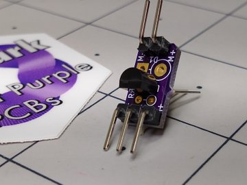
QRP-Labs filter adapter for NanoVNA
I had a few QRP-labs lowpass filters and bandpass filters kits laying around and because I had nothing better to do this afternoon, I fired up the soldering station and assembled them. After that they need to be tested and tuned.
Owning a NanoVNA for a few months now (and hardly use it because for antenna stuff i use my RigExpert AA-600), I decided to use the NanoVNA for tuning the filters. So from some pieces out of my junkbox (a piece of double sided pcb, 2 sma chassis and a header cut in 2) I build this simple filter holder allowing me to test and tune the filters to my requirements.
Adding the 3D printed base plate, hooking it with my NanoVNA.
Doing the calibration routine.
And ready for testing.
As expected like the previous design. But now no aditional PCB for calibration.
Can only say that the purple on yellow looks cool 🙂
For those who want a adapter, checkout my ForSale page.
We are excited to see this awesome project from Cedar Grove:
https://twitter.com/CedarGroveMakr/status/1271209134713528326
From Roger Cheng on Hackaday:

The main character of Dexter’s Laboratory is a genius child inventor who inspired a lot of fans to become makers and inventors in their own right. [Jorvon Moss] a.k.a. [Odd_Jayy] counts himself as one of them. A serial companion bot builder, his projects are constantly evolving. But every once in a while he pauses long enough to share construction details. Like how we can build our own monkey companion bot Dexter named after the cartoon.
A slightly earlier iteration of Dexter attended Hackaday Superconference 2019. Perched on [Odd_Jayy]’s back, Dexter joined in a presentation on companion bots. We’ve been a fan of his work since Asi the robot spider and several more robots have been posted online since. Recently at Virtually Maker Faire 2020, he joined [Alex Glow] and [Angela Sheehan] to talk about their respective experiences Making Companion Bots.
[Odd_Jayy] starts with sketches to explore how a project will look and act, striving to do something new and interesting every time. One of Dexter’s novelties is adding interactivity to companion bots. Historically people couldn’t do much more than just look at a companion bot, but Dexter can high five their fans! Sometimes the excited robot monkey ends up slapping [Odd_Jayy] instead, but they’re working through issues in their relationship. Everyone is invited to see rapid cycles of iterative improvements on Twitter and Instagram. As of this writing, a mini Dexter is underway with design elements similar to the “Doc Eyes” goggle project running in parallel. It’s always fun to watch these creations evolve. And by openly sharing his projects both online and off, [Odd_Jayy] is certainly doing his part to inspire the next wave of makers and inventors.
via Dexter the Companion Bot Wants To Give You Five — Hackaday
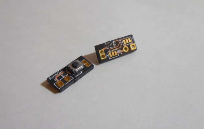
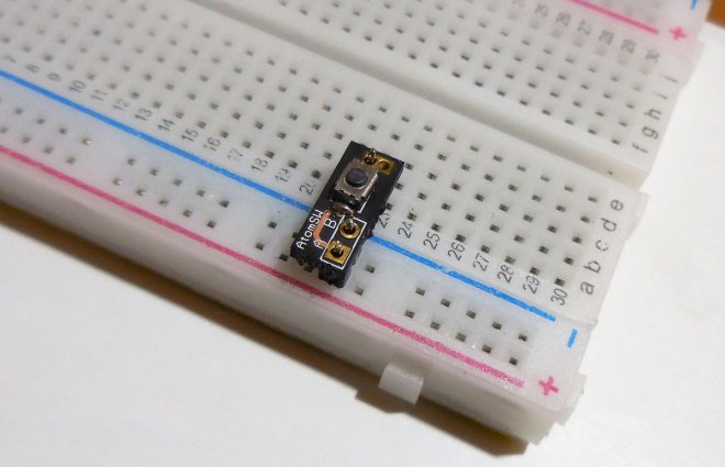
AtomSoftTech has a convenient little board to make it easy to connect a tact switch to a breadboard:
What is it?
A button you can be glad to have.
Why did you make it?
There isnt a small breadboard-able button out there with the features on this one.
What makes it special?
You have a selectable Pull-Up or Pull-Down and selectable High Output or Low Output. Using simple solder jumpers you can select between Pull up or Pull Down and what is the output of the button. All in a TINY PCB takinng almost no space on your PCB. No need to wire anything its breadboard friendly. Connects to the power rails and data side as well