When the tool you need doesn’t exist, you have to make it yourself. Come to think of it, even if the tool exists, it’s often way more fun to make it yourself. The former situation, though, is one that [Sean Hodgins] found himself in with regard to threaded inserts. Rather than suffer from the wrong tool for the job, he machined his own custom threaded insert tool for his Hakko soldering iron.
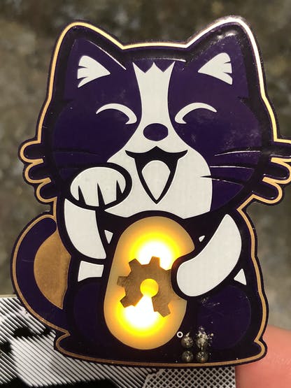
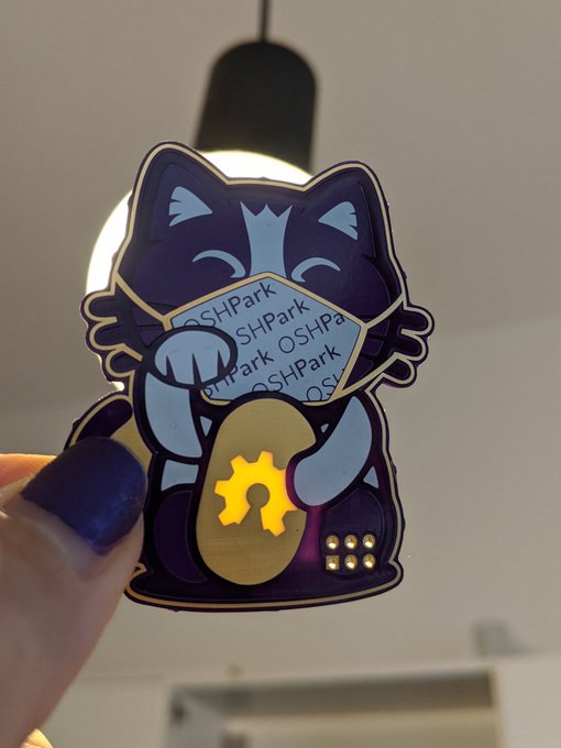
These adorable purple kitty PCBs by @mrtwinkletwink made it to my (notoriously unreliable) postbox in Berlin today. It's never a bad day when an @oshpark envelope turns up 💜✨ pic.twitter.com/m5AhfKtich
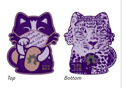
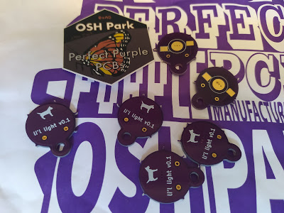
An updated Lucky OSHCat SAO featuring the latest SAO standard connection and a cute OSHPark themed Mask. Wear your mask in public, it’ll save yours and other’s lives.
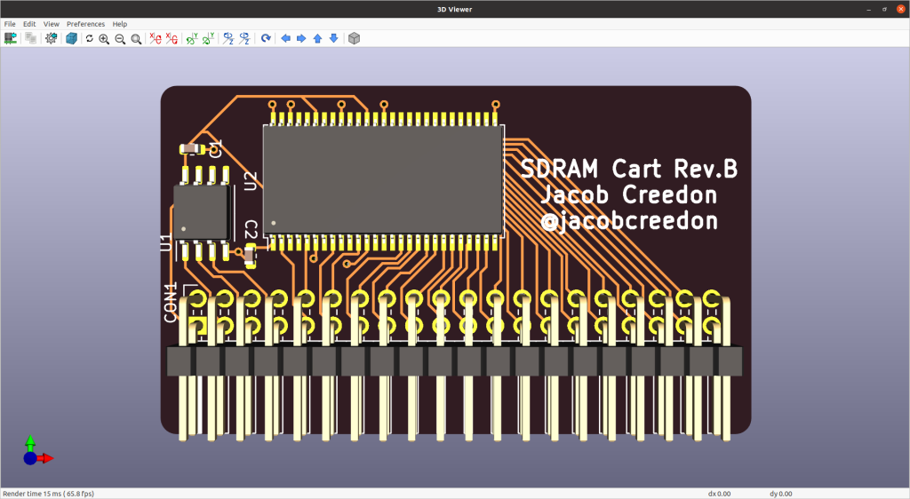
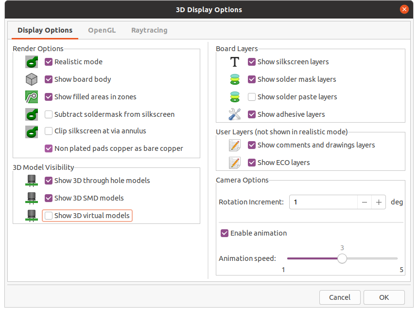
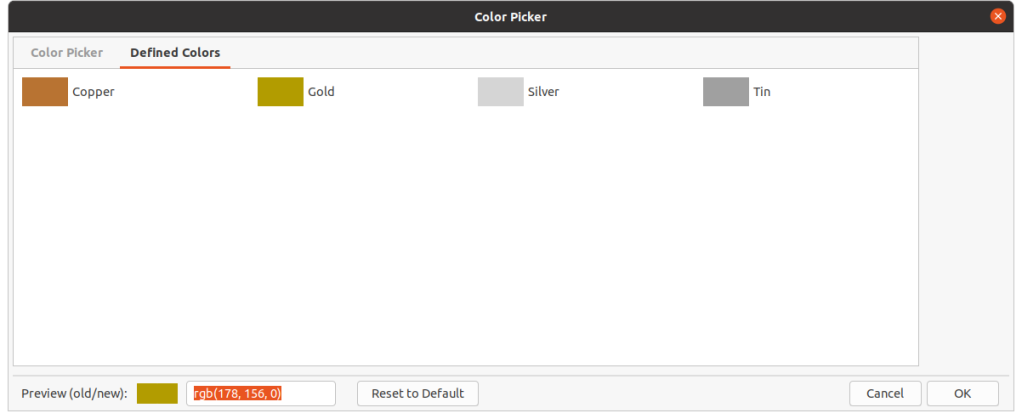
The KiCad 3D Viewer has seen a few incremental improvements during the course of V6 development:
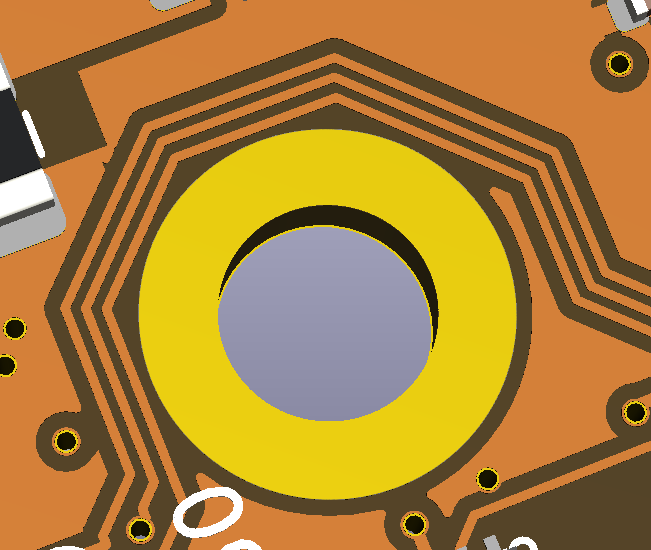
Plated and Non-Plated Copper
A subtle change has been made in MR#405 by Mario Luzeiro that affects how copper is rendered. The visual difference between plated copper pads and non-plated copper pads will now be visible as well as copper in general.
This image shows a ENIG plated copper hole compared to the surrounding copper traces when the soldermask was turned off.
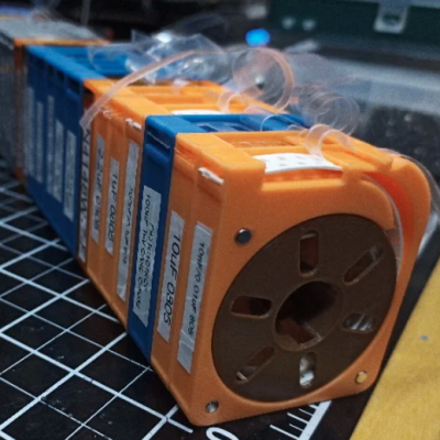
[Kadah]’s solution for storing short tapes of SMT parts is as attractive as it is clever. The small 3D-printed “tape reels” can double as dispensers, and stack nicely onto each other thanks to the sockets for magnets. The units come in a few different sizes, but are designed to stack in a consistent way.
We love the little touches such as recessed areas for labels, and the fact that the parts can print without supports (there are a couple of unsupported bridges, but they should work out fine.) Also, the outer dimensions of the units are not an accident. They have been specifically chosen to nestle snugly into the kind of part drawers that are a nearly ubiquitous feature of every hardware hacker’s work bench.
STLs are provided for handy download but [Kadah] also provides the original Fusion 360 design file, with all sizes defined as easily-customized parameters. In addition, [Kadah] thoughtfully provided each model in STEP format as well, making it easy to import and modify in almost any 3D CAD program.
Google Summer of Code or short GSoC came to an end for this years season recently and here we want to showcase some of the cool projects students work on this year around the AXIOM camera.
AXIOM Remote: Bootloader improvement and extensions
“The task was split up in the following sub-tasks:
– Flashing of the PIC16 firmware using the PIC32 bootloader
– Self-programming of PIC32: In simple terms it basically means to flash the firmware-with-UI on the PIC32 microcontroller
– Establishing the communication between the bootloader and the firmware
– Power saving modes for PIC32, LED dimming etc.
I created a python script which runs on the host PC and it can take care of the first two sub-tasks. The user can select the connected USB-UART port, HEX file to flash and the operation to perform. The project proposal, code links and the phase-wise report are given here on the Project Wiki page.” – Priya Pandya (MetalDent)
When working with hardware, whether a repair or a fresh build, it’s often necessary to test something. Depending on what you’re working with, this can be easy or a total pain if you can’t get the right signal to the right place. To eliminate this frustrating problem, [WilkoL] built a useful pulse generator for use in the lab.
[WilkoL] notes that historically, the job of generating pulses of varying length and frequency would be achieved with a smattering of 555 timers. While this is a perfectly cromulent way to do so, it was desired to take a different approach for the added flexibility modern hardware can offer. The pulse generator is instead built around an STM8 microcontroller; an unusual choice in this era, to be sure. [WilkoL] specified the part for its incredibly low cost, and highly capable timer hardware – perfect for the job.
Combined with an ST7735 TFT LCD screen, and programmed in bare metal for efficiency’s sake, the final project is installed in a project box with controls for frequency and pulse length – no more, no less. Capable of pulse lengths from 250 ns to 90 s, and frequencies from 10 mHz to 2 MHz, it’s a tool that should be comfortable testing everything from servos to mechanical counters.
OSHWA is looking for 5 new faces to join the board of directors for the Open Source Hardware Association.
The nominee form is, as always, for self-nominations only. Please fill out the nominee form (deactivated 11:59PM ET on Oct. 10th) to become a nominee or forward the link to someone you want to nominate. Do not fill out the form for someone else. The purpose of this form is to tell voting members why you want to serve on the OSHWA board. We will be publish the nominees and their answers on Oct 12th. Board members hold a 2-year position. Once board members have been chosen by the community, the board will appoint a President, VP, and Secretary. Board responsibilities include fundraising, advising on goals and direction, and carry out compliance with the organizations purposes and bylaws. See the board member agreement to get a sense of the responsibilities. Board members are expected to adhere to the board attendance policy and come prepared having read the board packet. Board members are expected to spend 5-10 hours of time per month on OSHWA. Nominees can submit questions to [email protected]. Nominations will be open until Oct. 10th.
After a successful first year of KiCon in 2019, we decided to change venues. We were very excited to hold the conference at CERN, a major contributor to the KiCad project. However, Coronavirus / COVID-19 changed a lot of plans, including ours. KiCon 2020 is completely remote, so that community members can still connect with the developers and each other. We will have a Developer component (coming up on Oct 3rd), and a Community component. Read on to hear more about each element, and sign up on the mailing list below so you keep up with the latest talks and speakers.
Since we will be all-remote this year, we’re kicking things off with a 2 hour discussion with the KiCad developers! You can hear about upcoming features for KiCad V6, get an update on the project, and ask your questions directly to the developers.
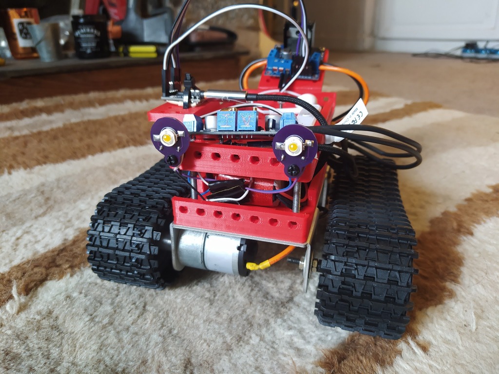
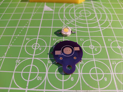
After designing the MTV robot I’ve been slowly tinkering with numerous add ons. I wanted to add some high power LED lights and so I bought some 1 watt white LED’s in an SMD package. They offered a lot of light and I’d read that the 1 watt LED didn’t need heatsinks to keep the running temperature within the datasheet operational temperature range.
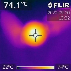
Testing them on the bench they get hot enough to be uncomfortable on the fingers so I decided that a PCB breakout that enabled them to be easily mounted but also acted as a slight heatsink was desirable. I quickly whipped up a design using the fabulous inkscape plugin SVG2Shenzhen and finished the design off in KiCAD . The PCB has a large pad that interfaces with the LED “slug” and in the PCB pad there are some via’s connecting that pad to the large copper flood on the back of the PCB. This flood is under the mask so heat doesn’t dissipate massively but I wanted it to just slightly reduce the temperature of the LED. When soldering on the LED I’ve added a small spot of thermal grease between the LED slug and the PCB pad. Finally I made sure that the M3 mount hole (3.2mm diameter for clearance) wasn’t copper plated so that hopefully the heat in the LED and PCB wouldn’t wick into mounting bolts etc.
I got some of the PCB made by the fantastic OSHpark and mounted up some LED. Driving them at 1 watt is made simpler by using one of the cheap constant current capable DC-DC buck driver boards that are readily available now. They certainly are bright!