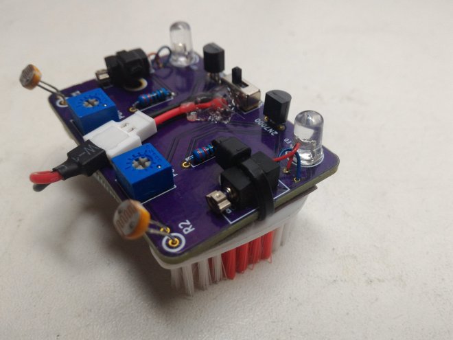
Bristlebots are great because no coding is required – they’re completely analog circuits that just go! But if you wanted them to go in a specific direction, how would you do that? Facelesstech has released their design for a light-following bristlebot that uses two LDRs to drive either side of the bristlebot (so you could turn it, somewhat – see video below for demo!). It’s pretty simple and pretty clever.
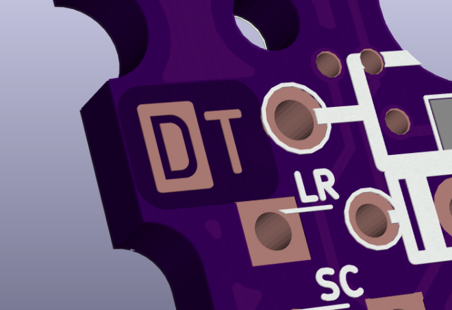
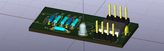
The KiCad design files are available on GitHub: