Digital Carburetor Sync Board

[Written by OSH Park engineer Jenner Hanni on Wickerbox Electronics]
IMG_2433

This was a collaboration with Tom Hogue (tz89 from the Venture Rider forum) to translate his prototyped design onto a printed circuit board. He’s done all of the software; my contributions were entirely in hardware.

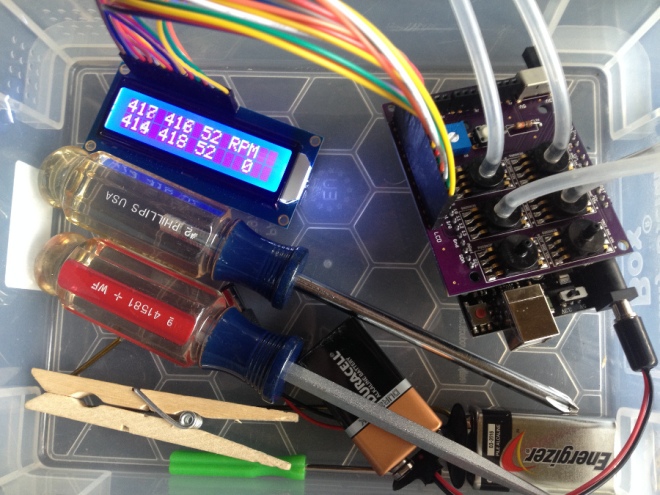
The Carb Sync Shield monitors the up to six carburetors and displays the vacuum pressure in realtime on an LCD display so the user can make adjustments to the air/fuel mix in each cylinder.

There’s an additional RPM feature that will be useful to set and monitor the idle speed on bikes that don’t have a tachometer.

The kit can be assembled by a novice using a basic soldering iron. The pressure sensors have extra-large surface mount pads and all other components are through-hole.

The shield is compatible with both the Arduino Uno v3 and the Bluetooth-capable RedBear Blend v1. It displays the RPM calculated from each of up to six simultaneous 3.3V or 5V pressure sensors on an LCD display which can be mounted directly or connected with the rainbow jumpers as shown above.

The board draws power from the carrier Uno or Blend board, which in turn can run off a 9V battery or a USB plug. The blue trim potentiometer controls the brightness of the LCD so it’s visible indoors or outdoors. The large switch sets the analog pressure sensor reference voltage to 3.3V or 5V. In the final version of the board, the switch is replaced with a 3-pin header and jumper cap.

Three digital I/O lines are broken out along with dedicated 5V or 3.3V pins to support extra sensors. It’s up to the user to match the sensor voltage on the digital line to the expected operating voltage of the Uno or Blend.

We had the boards fabricated through OSH Park, a local batch PCB service based in Oregon, and did a successful test in early November on Tom’s bike.

Digital Carburetor Sync Board

ESP8266 Flight Controller

2016-03-02T05-15-12.793Z-ESCFC.copter1.jpg.2560x2560_q85.jpg

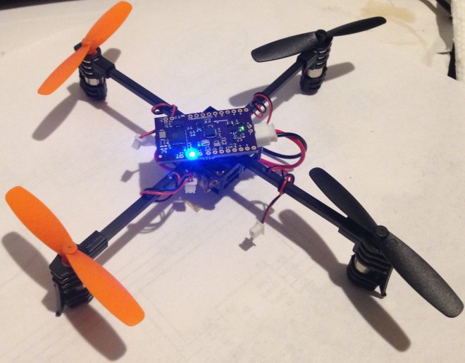
Kris Winer of Pesky Products designed a brushed motor UAV flight controller using the ESP8266:

ESP8266 Flight Controller

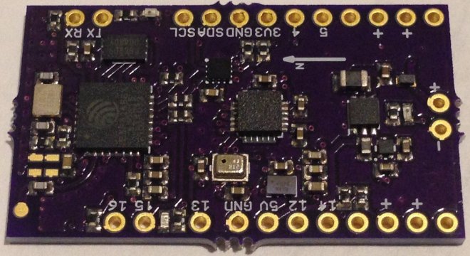
UAV flight controller [..] using the ESP8266EX Tensilica Xtensa system-on-chip, the EM7180+MPU9250+MS5637 (Ultimate Sensor Fusion Solution) for motion sensing and low on-resistance (20 mOhm) n-type DMN2041L MOSFets to drive up to four brushed motors using PWM signals

2016-03-02T03-11-40.889Z-ESCFC.top.08.jpg.2560x2560_q85.jpg

PeskyProducts has shared the board on OSH Park:

ESP8266FlightController.v02b

b5c5510641aee30dbc0a4e303e52a0c1

Order from OSH Park

ESP8266 Flight Controller

3G Cellphone Prototype

[Written by OSH Park engineer Jenner Hanni on Wickerbox Electronics]

finalboard.jpg

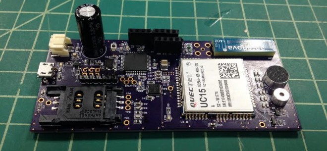
David A Mellis designed a DIY 2G Cellphone using the Quectel GSM/GPRS M10 2G module and the Arduino GSM Shield library. I updated David’s design with his permission and replaced the M10 with a Quectel UMTS/HSDPA UC15 3G module.

The modules have different pinouts, slightly different packages, and the UC15 takes 3.3V-4.3V while the M10 took 3.3V-4.6V, which accommodates a 3.7V LiPo battery.

I got the boards back and did an initial build, then handed things over to a local software developer who developed and presented the working cellphone at !!Con:

The Eagle schematic and layout, along with the development notes and bill of materials are available for the first version of the hardware:

Vocabulary

  • GSM – Global System for Mobile Communications, 2G
  • GPRS – General Packet Radio Services, packet data service on 2G and 3G
  • UMTS – Universal Mobile Telecommunications System, 3G
  • HSDPA – High-Speed Downlink Packet Access, allows 3G speeds

Reference

“GSM (Global System for Mobile Communications, originally Groupe Spécial Mobile), is a standard developed by the European Telecommunications Standards Institute (ETSI) to describe protocols for second generation (2G) digital cellular networks used by mobile phones.” -Wikipedia

“General packet radio service (GPRS) is a packet oriented mobile data service on the 2G and 3G cellular communication system’s global system for mobile communications (GSM).” -Wikipedia

“UMTS specifies a complete network system, which includes the radio access network (UMTS Terrestrial Radio Access Network, or UTRAN), the core network (Mobile Application Part, or MAP) and the authentication of users via SIM (subscriber identity module) cards.” -Wikipedia

“High-Speed Downlink Packet Access (HSDPA) is an enhanced 3G (third-generation) mobile-telephony communications protocol in the High-Speed Packet Access (HSPA) family, also dubbed 3.5G, 3G+, or Turbo 3G, which allows networks based on Universal Mobile Telecommunications System (UMTS) to have higher data-transfer speeds and capacity.” -Wikipedia

License

This project is released under the MIT License. Click here for more information.

3G Cellphone Prototype

Monitor plants with Bluetooth LE

Cmoa9VgWcAAScTZ.jpg
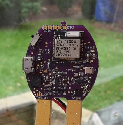
JamesCannan created a simple way of monitoring plants with Bluetooth Low Energy (BLE):

Easy Planter

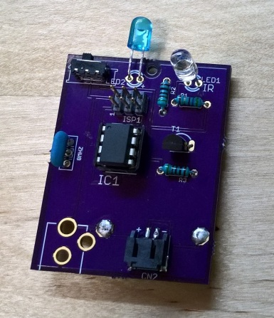
Monitor temperature, humidity, pressure, moisture, light, and has I2C extension pins so that you can add other modules. Information is sent to a phone, and notifies you when it needs something.


The EAGLE schematic and board layout are hosted on GitHub:

github Cannonball2134/EasyPlanter

Monitor plants with Bluetooth LE

Tiny, robust, low cost, fail-safe LED driver: the Glighter-S project — ALEA

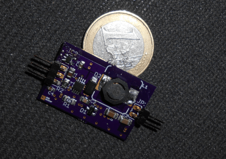
It has been a while since the last LED related article. Was experimented the linear current source, its pros and cons and the field of application. Now arises the need of a small version, handling the same high power, things that are contrapposed in the linear regulator. I need something that I can bring with […]

via Tiny, robust, low cost, fail-safe LED driver: the Glighter-S project — ALEA

Tiny, robust, low cost, fail-safe LED driver: the Glighter-S project — ALEA

STM32F303 + ice5 Development Board

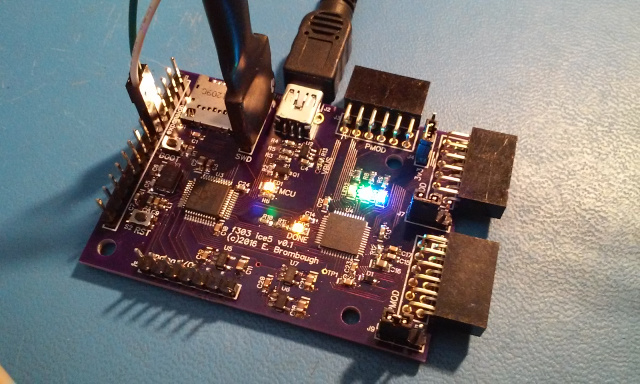
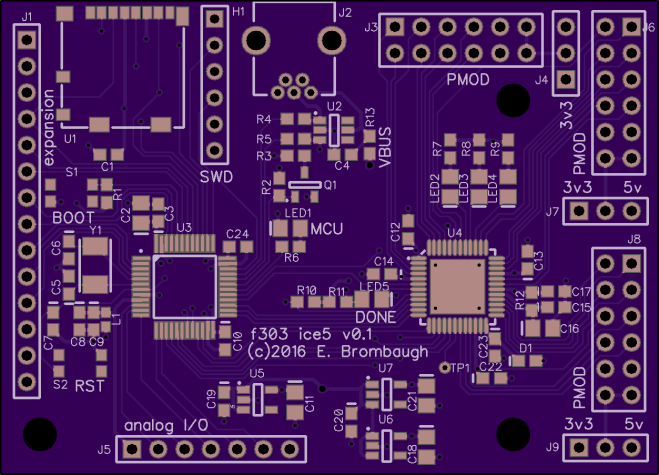
Eric Brombaugh designed this board which pairs ARM Cortex M4 processor with a Lattice FPGA:

f303_ice5

STM32F303 + ice5 Development Board

USB, Micro SD, PMOD and GPIO interfaces allow development of complex projects in control and signal processing.

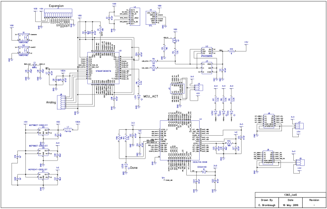
Schematic Diagram

sch.png

  • STM32F303CCT6 microcontroller:
    • 32-bit ARM Cortex-M4F CPU rated for 72MHz clock
    • 48kB SRAM, 256kB Flash
    • 10 Timers
    • 3x SPI, 2x I2S, 2x I2C, 3x USART
    • 1x CAN, 1x USB Device
    • 37 GPIO pins (20 5V tolerant)
    • 4x 12-bit SAR ADC, 2x 12-bit DACs
    • 7 Analog Comparators, 4 Op-Amps
  • Lattice iCE5LP4K-SG48 FPGA:
    • 3520 LUTs
    • 4 Multiplier/Accumulate blocks
    • 20x 4kb RAMs
    • OTP Non-volatile configuration memory
    • 1 PLL, 2x I2C cores, 2x SPI cores

The microcontroller firmware and FPGA hardware source is hosted on GitHub:

github emeb/f303_ice5


emeb has shared the board on OSH Park:

f303_ice5

124aa008272afeee0ce2d3c70dbaa45f

Order from OSH Park

STM32F303 + ice5 Development Board