
KiCad class starts July 7th

Anool Mahidharia will be teaching an introduction to KiCAD and FreeCAD:
https___cdn.evbuc.com_images_103358060_360176848959_1_original

Classes are Tuesdays at 19:00 IST. Classes are recorded and released on the course page within a few weeks so you can learn at your convenience. Office Hours are Fridays at 1630 IST and limited to 30 people per session. A second session in evening PDT will be offered August 2020.

The complete course is 4 classes long. For those who would like to attend each class, please sign up for each class individually.

Overview: We’ll start off with a hand drawn schematic, and progress from schematic capture to creating production files such as Gerbers, BoM, and 3D CAD export. We’ll then switch to FreeCAD and do a simple enclosure design for our project.

Schedule: The course will consist of four sessions total. Each section will contain a video component and an office hour component where the instructor will be available for questions.

Prerequisites: It will help to have a good understanding of electronics and some basic understanding of engineering drawing.

KiCad class starts July 7th

This SD Card Won’t Slot

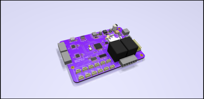
If you’ve got a few self-designed PCBs under your belt, you probably know the pain of missing some little detail and having to break out the bodge wires to fix it. So we feel for [Arsenio Dev], who placed an SD card slot next to an SoC, only to find that it was the wrong way round. Rather than tossing it in the bin, he decided to employ a particularly crafty set of bodge wires that curve over the board and connect to an SD card adapter on the other side.

Our attention was taken by the board itself, he’s posted little information about it and taken pains to conceal one of the pieces of text on it. Since it has an Octavo Systems BeagleBone-on-chip, a slot for a cellular modem, and a connector marked “CONNECT AERONET HERE” which we are guessing refers to the Aeronet sun photometry network, we’re guessing it might be a controller for remotely-sited nodes for that system. Either way it’s enough to have us intrigued, and we wish him every success with the next spin.

via Fail Of The Week: This SD Card Won’t Slot — Hackaday


Quote

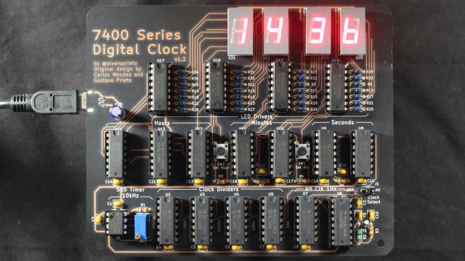
Reloj: 7400 Series Digital Clock

Alvaro Prieto makes great use of “After Dark” in this digital clock project:

Reloj: 7400 Series Digital Clock

This project was inspired by my dad’s university digital systems project from the late 1970’s. I found the writeup and schematic and decided to try and re-create it. You can see the results of the breadboard reproduction and explanations in this twitter thread.

After a while, I figured it would be fun to make a soldering kit out of it, which resulted in this.

IMG_6960

The design is fairly close to the original, but with the addition of a crystal-backed alternate clock source. The 555 timer cock source works, but drifts like crazy, so if you want to use it as an actual clock, you still can with the alt source.

Paper front page

Papers

If you want to take a look at the actual paper, you can see the scanned version here.

Design Files

You can get the latest files in the github releases.

For v1.2, you can use my OSHPark shared project or by grabbing the gerbers from the release.

Assembly Instructions

You can find semi-detailed assembly instructions here.

Reloj: 7400 Series Digital Clock

Tidy Laser Cut Packaging For PCBs With KiCAD

A laser cutter is a useful tool to have in any workshop. While many hackers use them for their cutting abilities, it’s important to remember that they can be great as engravers, too. [Wrickert] was well aware of this when he set his to work, producing attractive packaging for his Tindie orders.

[Wrickert] sells a variety of small PCB-based devices on Tindie, and it’s nice to have something to package them up with, rather than just sending a bare board. To do this quickly and effectively, KiCAD is used to help generate the packaging from the original PCB geometry itself. The board outlines are exported as an SVG file, reopened in KiCAD, and then used to create the required cardboard parts. The laser can then also be used to engrave the cardboard too.

It’s a tidy packaging solution that requires no messy inks or printers, and can be designed in the same software as the device itself. We’ve covered this area before, talking about what it takes to go from a home project to a saleable kit. If you’re in the game, you might find [Wrickert]’s hack to be just the ticket!

via Tidy Laser Cut Packaging For PCBs With KiCAD — Hackaday

Quote

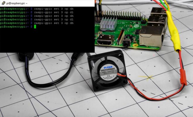
Raspberry Pi Cooling Fan Control with Bash Scripting

In a previous post, I did a very brief introduction to the world of Bash scripting in the context of Raspberry Pi single-board computers. It’s an amazingly powerful tool, capable of administrative tasks like batch file renaming, making decisions, and more. While this scripting interface is available for any Linux system, the Raspberry Pi’s GPIO pins make it even more powerful, allowing it to control physical devices, like an LED directly, or even motors and other higher current devices indirectly via a transistor.

As it just so happens, the Raspberry Pi doesn’t come with any sort of active or even passive, cooling solution, and it’s pretty common to simply hook up a fan to run at all times to its 5V power supply. This seems to work fine, but when I noticed the Pi that runs my 3D printer (in a hot Florida garage) was overheating, running it all the time seemed a little silly. After all, power is applied to the Pi constantly, but it’s actually used on a very intermittent basis when I’m printing something.

(Script and PCB design available on GitHub)

Raspberry Pi Cooling Fan Control with Bash Scripting

Adding PCIe To Your Raspberry Pi 4, The Easier Way

raspberry_pi_4_installed_pcie_bridge

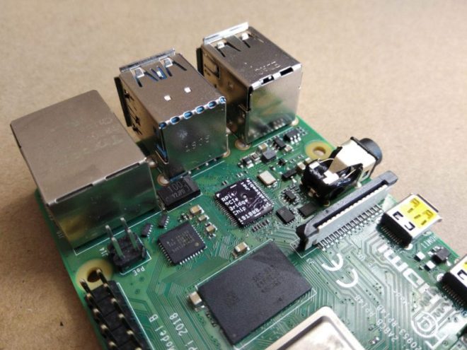
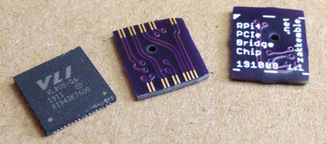
Ever since people figured out that the Raspberry Pi 4 has a PCIe bus, the race was on to be the first to connect a regular PCIe expansion card to a Raspberry Pi 4 SBC. Now [Zak Kemble] has created a new approach, using a bridge PCB that replaces the VL805 USB 3 controller IC. This was also how the original modification by [Tomasz Mloduchowski] worked, only now it comes in a handy (OSHPark) PCB format.

rpi4_bridge_chip-1024x454-1

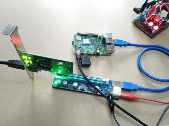
After removing the VL805 QFN package and soldering in the bridge PCB, [Zak] confirmed that everything was hooked up properly and attempted to use the Raspberry Pi 4 with a PCIe extender. This showed that the Raspberry Pi would happily talk with a VL805-based USB 3.0 PCIe expansion card, as well as a Realtek RTL8111-based Ethernet card, but not a number of other PCIe cards. Exactly why this is is still unclear at this point.

raspberry_pi_4_pcie_expander

As a bonus, [Zak] also found that despite the removal of the VL805 IC from the Raspberry Pi rendering its USB 3 ports useless, one can still use the USB-C ‘power input’ on the SBC as a host controller. This way one can have both PCIe x1 and USB on a Raspberry Pi 4.

This is the third iteration we’ve seen for using PCIe with the Pi. If you’re building on the work of [Thomasz Mloduchowski], which inspired [Colin Riley] to add expanders, and now this excellent hack by [Zak], we want to hear about it!

via Adding PCIe To Your Raspberry Pi 4, The Easier Way — Hackaday

Quote

OSHWA: A Resolution to Redefine SPI Signal Names

The Open Source Hardware Association (OSHWA) has just posted:

pasted image 0

A Resolution to Redefine SPI Signal Names

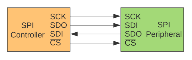
We, the undersigned, encourage educators, engineers, designers, and community members to discontinue the use of the terms MOSI/MISO/SS and in their place use SDO/SDI/CS.

  • New signal names:
    • SDO – Serial Data Out. An output signal on a device where data is sent out to another SPI device.
    • SDI – Serial Data In. An input signal on a device where data is received from another SPI device.
    • CS – Chip Select. Activated by the controller to initiate communication with a given peripheral.
    • COPI (controller out / peripheral in). For devices that can be either a controller or a peripheral; the signal on which the device sends output when acting as the controller, and receives input when acting as the peripheral.
    • CIPO (controller in / peripheral out). For devices that can be either a controller or a peripheral; the signal on which the device receives input when acting as the controller, and sends output when acting as the peripheral.
      SDIO – Serial Data In/Out. A bi-directional serial signal.
  • Deprecated signal names:
    • MOSI – Master Out Slave In
    • MISO – Master In Slave Out
    • SS – Slave Select
    • MOMI – Master Out Master In
    • SOSI – Slave Out Slave In
  • Signal names unchanged:
    • SCK – Serial Clock. The clock for the bus generated by the controller.

Designers should avoid signal names MOSI/MISO and instead use SDO/SDI. The SDI signal is defined by the perspective of the device. For example, the SDI signal on a sensor is the pin that receives data from the controller. Similarly, the SDO pin on a controller is the output pin that sends data to a peripheral.

It is best practice to use SDO/SDI and Controller/Peripheral. Change the way you write tutorials, create schematics, and diagrams. This is the best way to educate the next generation of users and engineers.

Read more..

OSHWA: A Resolution to Redefine SPI Signal Names

Tips for automatic testing equipment

Tom Fleet writes on Hackster:

Are You Shelling Out Too Much on ATE? Has a Few Tricks to Help You Claw Back Some Margins!

Anyone of us can build something.

Fewer of us, myself included, excel at building a great number of something, and when it comes to scaling a design to any level of volume production, it quickly becomes obvious that in order to save your sanity, the only sensible option is to outsource the onerous process of production to an OEM, or similar set of subcontracted companies, that can handle the production of your products.

Some of them make designing the board seem like the easy bit. You’ll need a clear and concise build pack, not only with the PCB data supplied in the preferred format of your fab house, but also preferably with clear supporting documents to illustrate any quirks of the design that might need explaining.

The BoM must be complete and well sourced, backup suppliers and all. And providing you can get a well assembled set of PCBA out the end of your subcontracted process, you then have the not insignificant task of verifying the work that has been done — you need to test, and program if required — this box of boards that you have been delivered.

The type of testng that you might apply to these boards is going to be dictated by what they do. For something such as a simple SAO, that might mean poking a bit of pin header, attached to a coin cell battery, into the required pins.

For a more complex board, such as the OrangeCrab FPGA development board, things can quickly start to get a bit more involved… There is a whole suite of functionality to validate — from the basics of bringing up the power supplies,to ascertaining the analog inputs, and finally booting a bit-stream, there’s a fair amount of functionality that needs that “final test” check mark.

Tips for automatic testing equipment

Agricoltura: connected control system for agriculture

Adam Vadala-Roth has posted on Hackaday.io about a connected control system for all agriculture applications based on RS485 control nodes and multiple wireless sensor networks:

8246911593228843731

Agricoltura

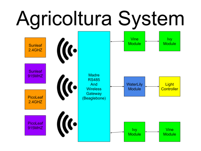
Agricoltura is the culmination of multiple projects I’ve worked on in the past related to the sensing and control of agriculture systems, notably HydroPWNics and SunLeaf.  Agricoltura aims to unite all the concepts of those past projects into a new system based primarily on RS485 nodes for control of pumps, sensor sampling, and light control.

The base system will be a gateway controller linked to daisy chainable RS485 nodes designed for specific functions. These nodes are built around a board called Vine.
Vine allows interfacing of QWIIC connect sensros and devices as well as relay control. Coming in as two varients Vine can be used to setup and control complete hydroponic farming systems or any other agriculture system.

4070251593134247670


Agricoltura: connected control system for agriculture

Virtual Toorcamp this weekend

Screenshot from 2020-06-25 12-46-43

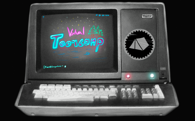
ToorCamp 2020 was originally scheduled for June 23rd-28th, 2020 but due to the COVID-19 Pandemic, it’s been postponed until July 14-18th 2021. Instead, we’ve decided to host VirtualToor the weekend of June 27-28th as a self-organized event with talks, village hangouts, contests, and project collaborations to help ToorCampers build up momentum on research and projects for the event next year.

If you have ideas for talks, projects, contests, or other virtual events, please go ahead and post to this wiki. We’ll follow up if there’s any conflicts or issues with the self-organized content.

Find out more!

Virtual Toorcamp this weekend