Max and Sebastian again dive into recent project developments like Google Summer of Code projects and the AXIOM Remote.
Once again apertus° participated in Google’s sponsored program for students working with open source projects like this one. Here is a brief insight into what was worked on this year for Summer of Code. Six student slots were filled with excellent applications and four students finished the program successfully.
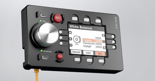
There has been good development progress in several areas with the camera control device, the AXIOM Remote. The device features a small display with graphical user interface, a central rotary encoder dial and physical buttons providing haptic feedback where a touchscreen (think smartphone app) simply couldn’t. There is an enclosure concept, electronics prototype and software running on the device prototype already.
If you hadn’t noticed, we had a bit of an FPGA theme running at this year’s Superconference. Why? Because the open-source FPGA toolchain is ripening, and because many of the problems that hackers (and academics) are tackling these days have become complex enough to warrant using them. A case in point: David Williams is a university professor who just wanted to build a quadruped robotics project. Each leg has a complex set of motors, motor drivers, sensors, and other feedback mechanisms. Centralizing all of this data put real strains on the robot’s network, and with so many devices the microcontrollers were running out of GPIOs. This lead him to become, in his words, “FPGA-curious”.
If you’re looking for a gentle introduction to the state of the art in open-source FPGAs, this is your talk. David covers everything, from a bird’s eye view of hardware description languages, through the entire Yosys-based open-source toolchain, and even through to embedding soft-CPUs into the FPGA fabric. And that’s just the first 18 minutes. (Slides for your enjoyment, and you can watch the talk embedded below the break.)
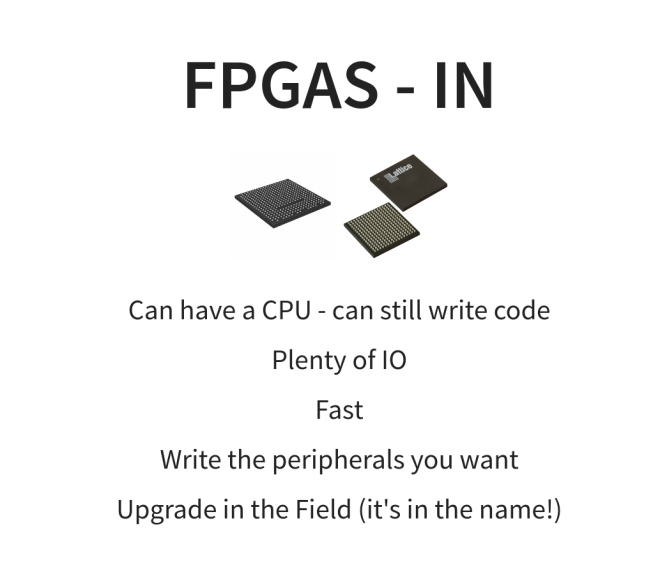
The second half of the talk is more about his personal experience and advice based on the last year or so of his experience going from FPGA newbie to master of his own robot. He highlights the versatility of a soft-CPU in an FPGA versus a pre-baked microcontroller solution. With the microcontroller you get all of the peripherals built into the silicon, but with the FPGA you get to write your own peripherals. Want a 10-wire SPI-like bus? Just code it up. Your peripherals are as simple or complex as you need them to be.
On the hardware side, David touts the PMOD standard (a man after our own heart!) and points out the large ecology of PMOD-compatible devices out there. Going for a plug-in solution also means that your engineering job is reduced to building a carrier board that can seat the FPGA brainboard of your choosing and interface it with a bunch of PMODs. It’s hard to get much simpler than that.
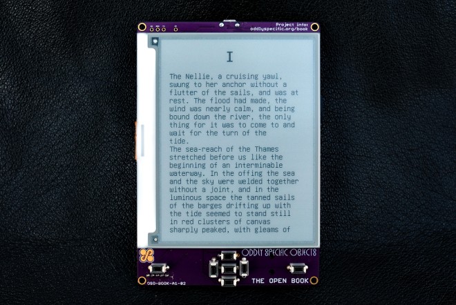
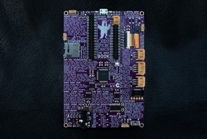
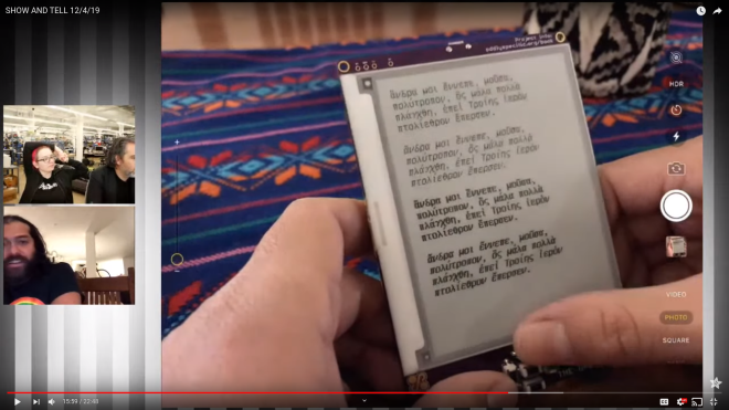
The Open Book is an open-hardware device for reading books in all the languages of the world. It includes a large screen and buttons for navigation, as well as audio options for accessibility and ports to extend its functionality. Its detailed silkscreen, with the all the manic energy and quixotic ambition of a Dr. Bronner’s bottle, aims to demystify the Open Book’s own design, breaking down for the curious reader both how the book works, and how they can build one for themselves.
At the core of the Open Book is a SAMD51J19A microcontroller, a powerful ARM Cortex M4 with 512 KB of Flash and 192 KB of RAM. It has 51 pins of GPIO, and the Open Book uses all of them for peripherals and possibilities:
A 400×300 black and white e-paper screen enables the core experience of, y’know, reading.
A MicroSD slot allows for plenty of external storage for files. An offline copy of Wikipedia fits in 64 gigs — Hitchhiker’s Guide, anyone?
User input comes from seven buttons on a shift register, plus an eighth button tied directly to one of the SAMD51’s interrupt pins.
A dedicated flash chip for languages gives the book room to store glyphs and Unicode data for every language in the Basic Multilingual Plane (which is most of the languages in use today).
The last two years has been a particularly exciting time for KiCad, for users, casual contributors, and for the core developers too. Even so, there are many cool new features that are still in process. One bottleneck with open-source development of complex tools like KiCad is the limited amount of time that developers can devote for the project. Action plugins stand to both reduce developer load and increase the pace of development by making it easier to add your own functionality to the already extensible tool.
Sometime around version 4.0.7 (correct us if we’re wrong), it was decided to introduce “action plugins” for KiCad, with the intention that the larger community of contributors can add features that were not on the immediate road map or the core developers were not working on. The plugin system is a framework for extending the capabilities of KiCad using shared libraries. If you’re interested in creating action plugins, check out documentation at KiCad Plugin System and Python Plugin Development for Pcbnew. Then head over to this forum post for a roundup of Tutorials on python scripting in pcbnew, and figure out how to Register a python plugin inside pcbnew Tools menu.
Since version 5.0, we’ve seen an explosion of extremely useful action plugins for KiCad that have added some very useful bells and whistles. The KiCad website lists a couple of external tools, but there’s a lot of action happening out there, so we decided to round up some of the more useful ones.
In the early days, PCB fabs often had yield issues due to offset drill holes, particularly on vias and micro-vias. One trick that PCB designers used to mitigate this problem was to use “teardrops”. The area around the pad or via that connected to the track was made into a teardrop shape, ostensibly in the hope that it would improve matters. Fabs nowadays do a pretty good job due to improved processes and accurate machines, so the jury is still out on the use of teardrops, but KiCad does have a Teardrop plugin, in case anyone wants to use it. Combined with smooth, rounded tracks, we’re guessing teardrops would be pretty helpful in the artistic PCBs department.
The Dutch organisation eth0 has run a series of informal small camps over the years, never with an attendance too far into three figures, and without pre-planned events or entertainment. What happens is at the instigation of the attendees, and the result is a weekend of much closer socialising and working together on projects than the large camps where you spend your time running around to catch everything.
The largest of hacker camps offer all the lights, robots, tschunk, and techno music you can stomach; they can be a blast but also overwhelming. I made my way eth0 over the past week weekend, enjoying the more intimate size and coming away having made friendships from spending time with great people at a large private camping hostel near Lichtenvoorde. This is in the far east of the country near the German border, to which in the company of a British hardware hacker friend I traveled in the tiny European hatchback. Netherlands roads are so easy to navigate!
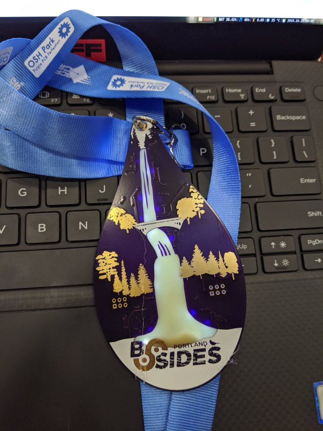
The badge itself has an interesting layout, because aside from a bit of badge.team and event related artwork it uses a multipurpose layout from Electronic Eel, that’s designed for both SMD and through-hole parts. This proved to be extremely versatile, but came with the slight burden that the through-hole pads were closely surrounded by the ground plane, making soldering a bit tricky. Despite this there was an enthusiastic take-up from camp attendees, with offerings that went well beyond the mundane.
For the majority of the attendees there was a badge bar, with plentiful supplies of LEDs ad other components. Some attendees made do with a pair of colour changing LEDs and a CR2032, but others made CMOS astable oscillators using 4093 Schmitt AND gates for the full flashing effect. It’s almost unexpected today when so much is done by microcontrollers to see people hacking logic gate oscillators, but there was a circuit bending element to it all that made for a more enjoyable experience.
A fully functional event badge built upon an event badge. Fuchsia’s Tamafoxi runs the badge.team firmware.
One or two badges sported extra lighting in the form of Neopixels and similar. This staple of the LED badge is the obvious choice for one like the eth0 badge, even with its relative lack of space. The piece de resistance of the eth0 winter 2019 badges though did not feature any LED lights, instead it came with a small OLED display and a set of buttons. Fuchsia’e Tamafoxi is a fully functional tamagotchi clone that runs under the badge.team badge firmware, for which a Wemos ESP32 board had been fitted to the back of the badge. Power wasn’t quite so elegant, requiring a small protoboard and LiPo cell sandwiched to the back of the badge, but for the feat of getting a badge that wouldn’t disgrace a much larger event running on what was in effect a fancy protoboard, we’ll forgive all that. Plenty of event badge teams have set out to achieve this level of functionality and not quite made it, so to do so on an event badge like this one is a very significant feat indeed.
This was a short camp by the standards of some others, starting on a Friday evening and wrapping up at Sunday lunchtime. We left in the drizzle of a damp autumn afternoon for the easy trip to the overnight ferry across the billiard-table-smooth Dutch motorways, without some of the stress of limited access while packing that comes with the larger camps. It had been everything we’d wanted from a small hacker camp and more, so speaking personally I’d certainly head back to this one if the opportunity arose.
To load data you need an EEPROM programmer and like the chips, these devices have become somewhat rare and expensive. Hence the project to build one ourselves.
The easiest approach is probably to use a microcontroller to bridge between the chip and a computer, run a bidirectional serial protocol between the microcontoller and the computer to send image data back and forth.
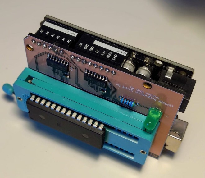
Since the AT28C256 requires 5v for writing, we can’t use a Raspberry Pi or Arduino Nano/Mini as their GPIO ports are all 3.3v. The regular old Arduino UNO is 5v though and so should work nicely.
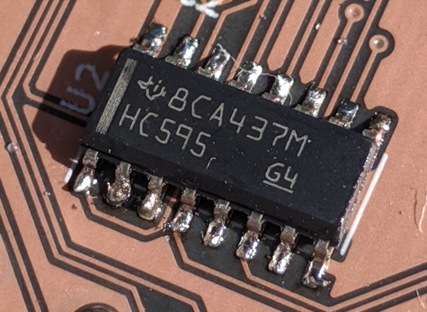
To gain some experience hand-soldering surface mount devices, I picked SMT packages for the shift registers and decoupling capacitors.
The ZIF socket is a 40 pin device I had lying around. Since the AT28C256 is a 28-DIP, I just left the 12 left-most pins unconnected. It’s a low budget project.
When I went to upload the Gerber files to OshPark for fabrication I noticed their “ After Dark “ option that uses a black FR4 substrate, with transparent soldermask that makes the copper traces pop against a black background.
The KiCad project as well as the serial protocol description and code for the Arduino and Python CLI can be found on on GitHub.
Printed circuits have become so commoditized that we seldom think much about design details. EDA software makes it easy to forget about the subtleties and nuances that make themselves painfully obvious once your design comes back from the fab and doesn’t work quite the way you thought it would.
PCB design only gets more difficult the faster your circuit needs to go, and that’s where a depth of practical design experience can come in handy. Bil Herd, the legendary design engineer who worked on the Commodore C128 and Plus4/264 computers and many designs since then, knows a thing or two in this space, and he’s going to stop by the Hack Chat to talk about it. This is your chance to pick the brain of someone with a wealth of real-world experience in high-speed PCB design. Come along to find out what kind of design mistakes are waiting to make your day miserable, and which ones can be safely ignored. Spoiler alert: square corners probably don’t matter.
Rarely during product development do you get it correct on the first design iteration. Something always goes wrong or just isn’t perfect. However, like trying for a hole-in-one on a par 3, you always try for perfection but expect to need a few extra strokes. So, while I almost hit a hole in one in the first version of the Nixie Tube HAT (Part 1), a few improvements were required. In this blog, I describe the few improvements found from Part 1 and complete the design to reach stage 6 of the surfncircuits defined development flow. As with the other projects in the blog, the complete design files in Kicad, schematics, layout, BOM, are available at GitHub for use in your own projects. You can build it yourself and the PCB can also be ordered directly from Oshpark.