The Pocket SP adds a hinge to the Game Boy

Allison Parrish wrote a detailed blog post about their Game Boy mod journey:

When to hold ’em and when to fold ’em: Adding a hinge to a Game Boy that God never intended

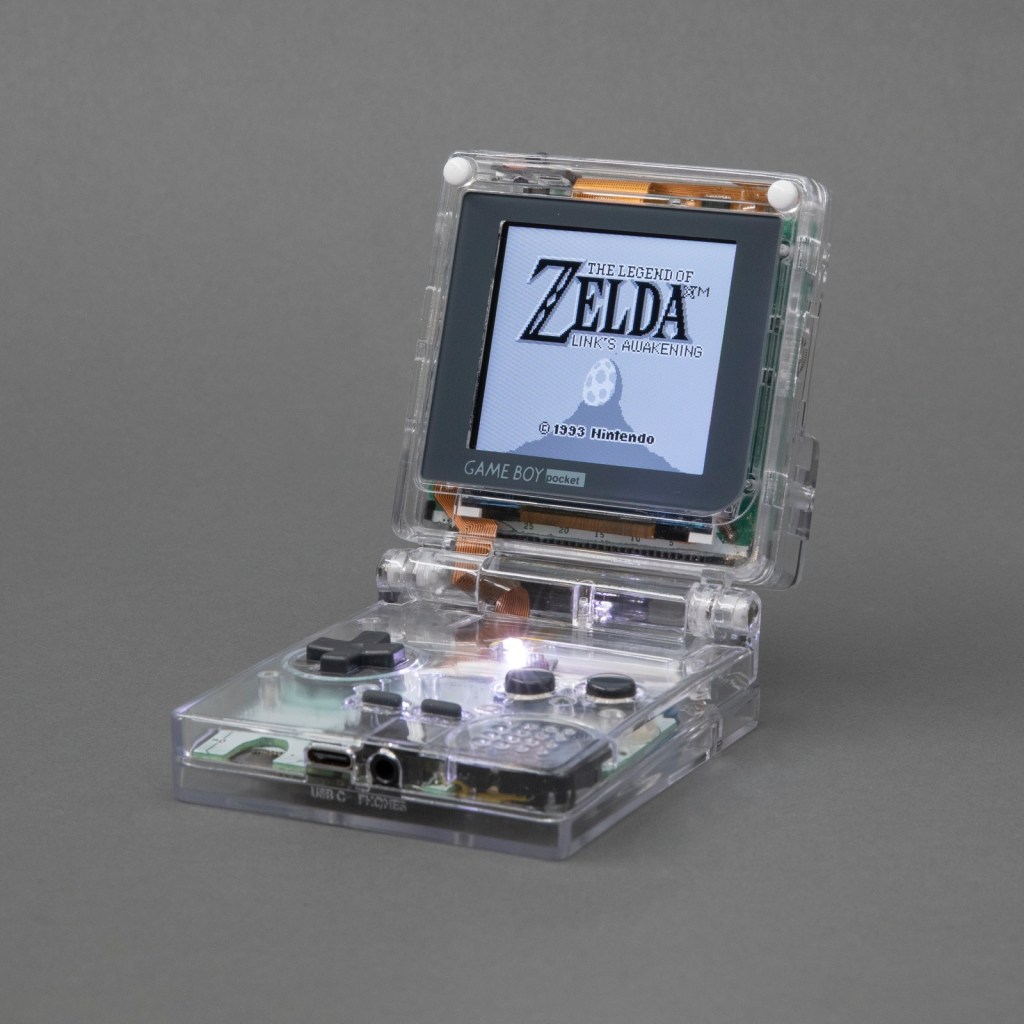
Over the summer I dug in deep with Game Boy modding and made this: the Game Boy Pocket SP. It’s a Game Boy Pocket motherboard that I cut in half and then put into a custom-designed shell with a hinge, a la the Game Boy Advance SP. The build has a pair of custom-designed flex PCBs to make routing signals between the two halves of the board easier. Along the way I taught myself CAD (with FreeCAD), PCB design (with KiCad) and 3D printing. The 3D models and PCB layouts for the Pocket SP are available on GitHub. In this post, I’m going to talk about why and how I made the Pocket SP, and how you can make your own.

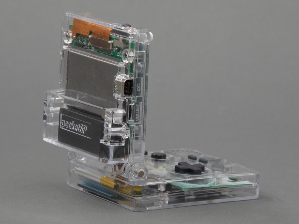
The design of a flexible PCB ribbon cable was key to the ability for the mod to fold up:

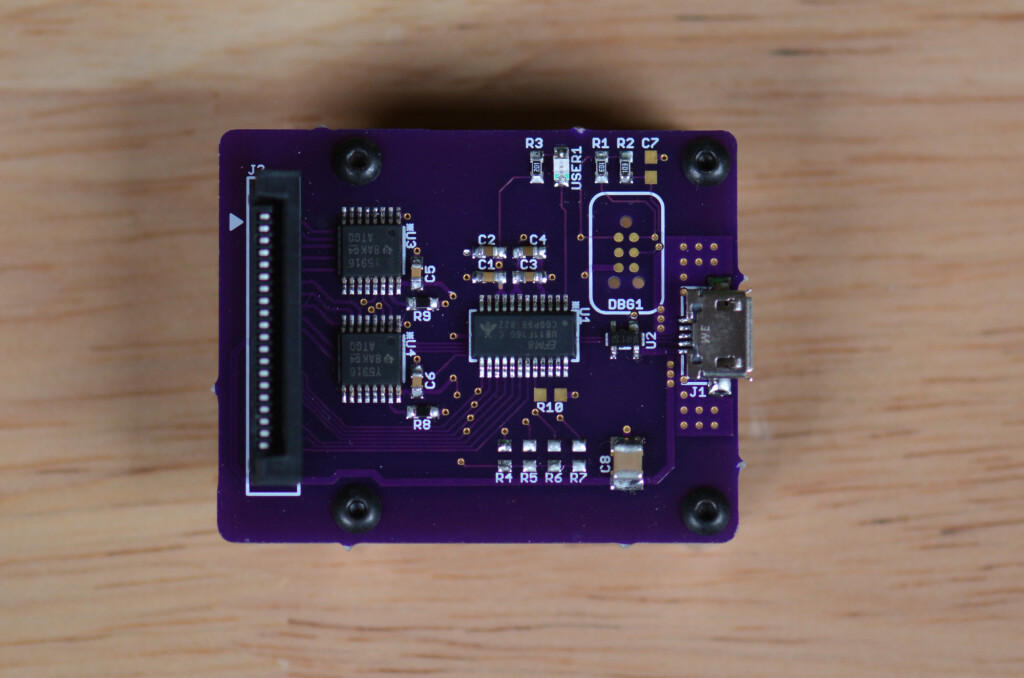
I designed a pair of flex PCBs that could be soldered directly to the board. One of the flex PCBs would end in a thin ribbon, which would go through the hinge assembly, and then connect to the other PCB with an FPC connector. This would make it easy to assemble and disassemble the unit, and would also make soldering pretty easy.

I think the closest I’d ever come to designing my own PCB was in grad school, when I downloaded EAGLE and never opened it and then deleted it at the end of the semester. But I’ve always wanted to design and fabricate my own PCB! I decided to use KiCad, because it’s free and open source and also the tool of choice for many modders in the community that I respect.

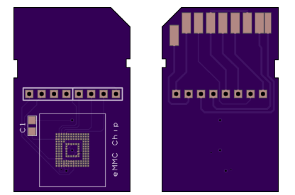
As with FreeCAD, the tutorial material for KiCad is pretty great. I spent an afternoon following along with the Getting Started guide and felt confident enough afterwards to actually start making my board. My schematic is pretty simple, since all I’m doing is connecting pads to headers and connectors.

Read more…

The Pocket SP adds a hinge to the Game Boy

Converting a vintage button panel to USB

Glen Akins (@bikerglen) writes about converting a vintage button panel to USB:

Converting a Vintage Grass Valley Button Panel to USB Using the Silicon Labs EFM8UB1

In this project, I convert a set of illuminated push buttons from a vintage Grass Valley video mixer into a custom vendor-defined USB HID peripheral. Like the USB analog panel meters project, this project uses a Silicon Labs EFM8UB1 microcontroller for USB connectivity. Unlike the panel meters project which only received data from the USB host, this project needs to send data back to the USB host too.

In this write up, we’ll reverse engineer the button panel, decide on a strategy for reading the keys and controlling the LEDs, build a board, then write both embedded and Linux software to interface with the button panel. If you want to build your own device like this but don’t have this specific switch panel, don’t worry–the ideas presented here are applicable to any generic 3×4/4×3/4×4 matrix keypad with or without LEDs.

Design files for this project are in my usb-led-switch-matrix repository on GitHub.

Converting a vintage button panel to USB

Handheld Apple IIe emulator powered by Teensy

Jorj Bauer has created a handheld Apple IIe emulator with a Teensy:

Aiie! – an embedded Apple //e emulator

Teensy 4.1 (600 MHz arm Cortex M7) running a full-speed Apple //e emulator. Because everyone needs one of these, right?

The OSH Park boards arrived, and I spent some time Monday assembling! Here’s a time lapse of the build, which took me shy of 3 hours (mostly because I hadn’t organized any of the parts and had to hunt for several).

Handheld Apple IIe emulator powered by Teensy

Multifunction Raspberry Pi Chiptune Player

https://youtube.com/watch?v=kB-iyDEXOrY%3Fversion%3D3

General Instrument’s AY-3-8910 is a chip associated with video game music and is became popular with arcade games and pinball machines. The chip tunes produced by this IC are iconic and are reminiscent of a great era for electronics. [Deater] has done an amazing job at creating a harmony between the old and new with his Raspberry…

via Multifunction Raspberry Pi Chiptune Player — Hackaday

Multifunction Raspberry Pi Chiptune Player

eMMC to SD Card Adapter

20170129_133109-s

From the Intelligent Toasters blog:

Retro CPC Dongle – Part 18

I’ve been working on, replacing the NAND raw flash with an eMMC chip on the CPC2.0 board.

20170129_135450-s

I wrote about raw flash and the challenges of writing a flash translation later in part 16 of this series. After some research, I concluded that the eMMC interface looked exactly like the much more common SDCard interface, albeit that the interface can be run with an 8-bit width. SDCards are limited to 4 bits by the physical pin count. Taking a gamble I created a board to test this new eMMC chip. I created a fake SDCard!

20170129_135518-s

This fake card allowed me to check very quickly if my assumptions were correct both at a hardware and a firmware level. I wanted to be sure that it was possible to interface the eMMC via 4 bits, rather than the full 8 bits and be sure the firmware instructions were the same between these two technologies.

Intelligent-Toasters has shared the board on OSH Park:

emmc.zip

screenshot-at-2017-02-15-21-04-11

Order from OSH Park

eMMC to SD Card Adapter