SparkFun MicroMod: New Modular Development Ecosystem

James Lewis writes on Hackster about how this new initiative from SparkFun will allow people to mix and match multiple 32-bit microcontrollers with a vast array of peripherals:

Get Connected with SparkFun’s MicroMod — A New Modular Development Ecosystem for Embedded Designs

SparkFun has just announced a new modular ecosystem called MicroMod. Targeting rapid embedded development, MicroMod consists of two pieces: a microcontroller board and a carrier board. The interconnect between the two is the PC industry’s M.2 connector.

Look at any embedded device’s block diagram, and you’ll see a microcontroller in the middle with a bunch of stuff surrounding it. That model is probably why the processor gets picked early in development. But, what happens when the design needs a microprocessor with a different architecture? Or unexpected capability, like WiFi, crept into the requirements? In the past, it would take significant effort to change either the processor or, worst case, the rest of the embedded system. With MicroMod’s approach, the hardware change is as simple as swapping modules.

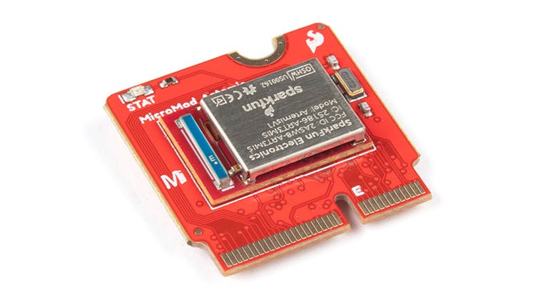
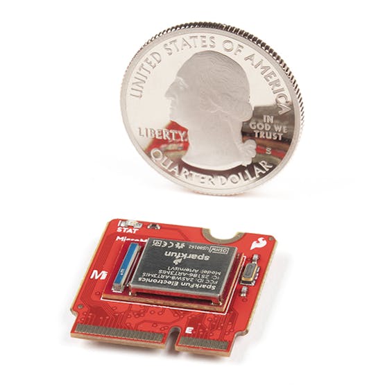
“The processor you start with is not always the one you end with … MicroMod makes exploring different microcontrollers easy.” — Nathan Seidle, SparkFun Founder
 

The most striking physical feature of MicroMod’s processor modules is the size. Their widths are similar to M.2 devices, but their lengths are much shorter. Each processor board contains very few components. For example, the ESP32 board has the SoC, an antenna, a flash memory, and the USB-to-serial chip. That is it! The carrier board contains extra things like a reset switch, voltage regulator, USB connector, and in-circuit programming header. With so much pushed to the carrier boards, it is no wonder SparkFun opted for a high-density, high-pin count, high-speed connector like M.2!

To be clear, while mechanically compatible with the M.2, MicroMod is not electrically compatible. Fortunately, SparkFun has open-sourced the pinout. That step makes it easy to use the pre-made modules or to design your own.

With today’s launch, there are three processor boards and four carrier boards available.

SparkFun MicroMod: New Modular Development Ecosystem

Audio Reactive Kitty Ears

Screenshot from 2018-04-10 12-04-10

Mary Etta West at SparkFun has remixed Anouk Wipprecht’s Kitty Ear project to make it react to audio:

Audio Reactive Wearables

At the beginning of this year I began prototyping an audio reactive headband to wear in my everyday life, like while dancing with my dog in my lab listening to Legend of Zelda dubstep.

Screenshot from 2018-04-10 12-07-34.png

 A few weeks ago I saw this post by my favorite Engineer/Maker/FashionTech Designer/Roboticist Anouk Wipprecht – a kitty ears soldering project with 3D-printed headband. I immediately ordered the Electronic Kitty Ears Headband from Shapeways, and after more digging around I found the Instructables tutorial for the kitty ears soldering project. The tutorial includes the BOM, the .stl files for the headband and a link to the OSHPARK shared project.

I downloaded the gerbers and exported the dimension layer as a gerber by itself. Then I imported it to the dimension layer in EagleCAD so I knew I had the same dimensions and my circuit would fit in the Kitty Ears headband. You can see the prototypes in the first picture. In a day I captured the schematic from the original prototype circuit and laid out the PCB design in the Kitty Ears form factor.

The design files and source code are available on GitHub:

AudioReactiveHeadBand

Audio Reactive Kitty Ears

Friday Hack Chat: How Do You Collaborate With Hardware?

Our guests for this week’s Hack Chat are Pete Dokter and Toni Klopfenstein of SparkFun Electronics. Pete is formerly the Director of Engineering at SparkFun and now the Brand Ambassador for SparkFun Electronics.

He hosts the According to Pete video series expounding on various engineering principles and seriously needs a silverburst Les Paul and a Sunn Model T. Toni is currently the product development manager at SparkFun. She’s served on the Open Source Hardware Association Board and participates in the Open Hardware Summit yearly. In her free time, she spends fifty weeks out of the year finding dust in her art and electronics projects.

via Friday Hack Chat: How Do You Collaborate With Hardware? — Hackaday

Friday Hack Chat: How Do You Collaborate With Hardware?

Rotary Encoder Breakout with Pull-up Resistors

rotary1.jpg

This breakout board designed in KiCad makes it easy to put a rotary encoder and pull-up resistors on a breadboard.  (Thanks to Enrico for the idea to add pull-up resistors).  The footprints on the back are meant for 1206 SMD resistors.  I choose 1K Ohm resistors, marked 102, when I assembled this board.

Additional photos are available in the GitHub repo’s images directory and in a Google Photos gallery.

Here is the OSH Park shared project for the board:

Rotary Encoder Breakout with Pull-ups

Screenshot from 2017-04-04 15-55-27

Order from OSH Park

The KiCad design files are available on GitHub:

github-smallpdp7/rotary-encoder-breakout

white

I used this KiCad symbol and footprint by Mike Cousins for a Sparkfun rotary encoder:

github-smallmcous/kicad-lib

white

I’ve verified that these rotary encoders fit:

I wrote this Arduino sketch to run on the Teensy 3.2.  The brightness of one LED is controlled by the rotary encoder knob.  The other LED is turns on when the rotary encoder knob is pressed down:

arduino-smallrotary-encoder-test.ino

white

Here’s a video of the breakout board being used with a Bourns PEC12R-4220F-S0024 and Teensy 3.2:

Rotary Encoder Breakout with Pull-up Resistors

Rotary Encoder Breakout Board

UPDATE: Check out the new version with pull-up resistors

img_20170211_233051

I designed this simple breakout board in KiCad to make it easier to put a rotary encoder on a breadboard.   The KiCad symbol and footprint for the SparkFun rotary encoder was created by mcous on GitHub.  I used an updated version with corrected pin numbering.

img_20170211_230723

Here are the rotary encoders that I’ve verified to fit:

img_20170211_233439

The design files are available on GitHub:

Screenshot at 2017-02-14 20-58-40.png pdp7/rotary-encoder-breakout

The board is shared on OSH Park:

SparkFun Rotary Encoder Breadboard Adapter

e1911a0b6c7595c4cd7a05c4806f83bf.png

Order from OSH Park

Rotary Encoder Breakout Board