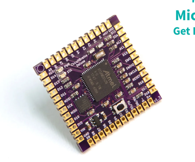
Easily Add a Powerful Microcontroller To Your Next Project
CircuitBrains Deluxe is the smallest soldererable ATSAMD51 module. Skip on all the tedious work of adding a 32-bit microcontroller to your next project. We’ve taken care of the tough work of pin mappings, power & decoupling layout, clock, flash, assembly, bootloader, and firmware. All you need to do is drop a footprint into your next PCB design project, connect your peripherals and USB connector, then solder it on and write your code.
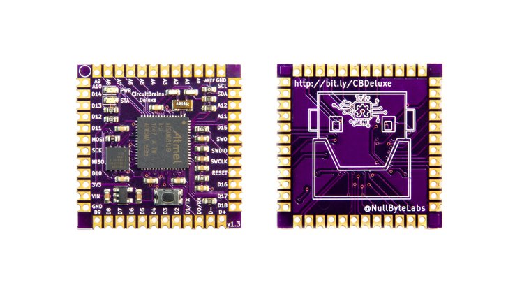
Just Solder It On
Save time and frustration on your next project. We’ve taken care of the finicky fine-pitch surface mount assembly for you. CircuitBrains comes in an easy-to-solder castellated module format. You can either incorporate it into your project PCB design, or solder wires directly to it via the extra holes in each castellated pad. We’ve also made it easier to hand solder these modules by including a larger “hand solder” PCB footprint for your design.
Add Some Power to Your Project
The core of CircuitBrains Deluxe is the Microchip ATSAMD51J19 32-bit ARM Cortex M4 microcontroller, which can run up to 120 MHz. In addition to a powerful microcontroller, each CircuitBrains Deluxe module has 8 MB of Quad SPI flash onboard. You’ll have plenty of space for your project code and media files.
Easy to Program
CircuitBrains comes preloaded with CircuitPython. Who doesn’t love Python on microcontrollers? Plug your device into USB, modify your code, and see the changes take effect as soon as you hit Save.
Small Form Factor
CircuitBrains Deluxe won’t take up a lot of space. It was designed to be used in small projects. At just over 1 square inch (29 mm), there aren’t many places this thing won’t fit into.
Author: fustini
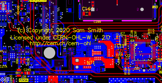
New CERN Open Source Hardware Licenses Mark A Major Step Forward
From Michael Weinberg on the Open Source Hardware Association (OSHWA) blog:
New CERN Open Source Hardware Licenses Mark A Major Step Forward
Earlier this month CERN (yes, that CERN) announced version 2.0 of their open hardware licenses (announcement and additional context from them). Version 2.0 of the license comes in three flavors of permissiveness and marks a major step forward in open source hardware (OSHW) licensing. It is the result of seven (!) years of work by a team lead by Myriam Ayass, Andrew Katz, and Javier Serrano. Before getting to what these licenses are doing, this post will provide some background on why open source hardware licensing is so complicated in the first place.
Gettting up and running with KiCad (April 8th)

Learn KiCad with Ayan Pahwa this Wednesday, April 8th, as listed on the Hackaday online classes and events calendar:
- 8:30 US PDT
- 11:30 US EDT
- 17:30 CEST
- 21:00 IST (India)
This KiCad forum post has more information:

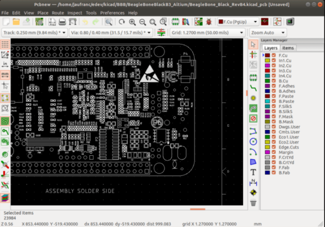
Altium Board importer for KiCad
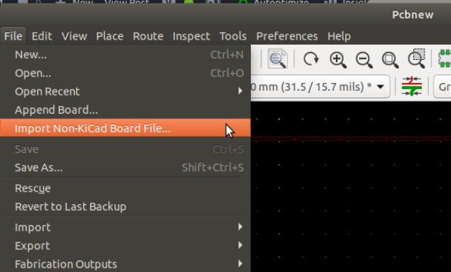
Thomas Pointhuber got Twitter excited yesterday with this video of importing Altium design into KiCad:
This is the foundation to add support for native Altium import. Contributions are very welcome, because this is a quite some amount of work.
The work is mainly based on https://github.com/thesourcerer8/altium2kicad, which is an existing Altium Designer -> KiCad converter written in Perl. Because Altium Circuit Studio and Altium Circuit Maker uses quite similar file formats, I try to support them as well in one go.
My current workflow is to try to understand the existing code, and build a binary documentation of the Altium format using Kaitai Struct. This allows fast iterations, and tells me if something is parsed incorrect.
CNX Software has a nice blog post on how to build the development version of KiCad:
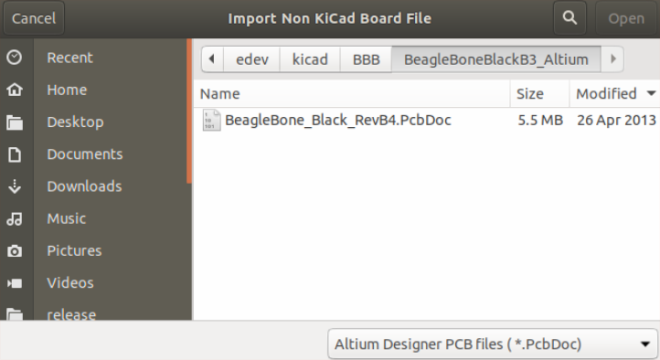
How to Build KiCad on Ubuntu 18.04 and Import Altium PCB Files
KiCad open-source EDA (Electronics Design Automation) suite software is now very popular, and many new projects are designed with the utility. AFAIK, some companies like Olimex switched all their new designs to KiCAD. But since many schematics and PCB layouts have been designed with other tools like EAGLE, Orcad Allegro, or Altium PCB design tools, it would be nice to be able to import those designs into KiCad.
PCB Artwork with Inkscape and KiCad
Anool is doing live streams every Saturday on KiCad and this week Bradan Lane joined to show how to use Inkscape to create PCB artwork:
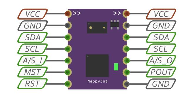
MappyDot Distance Measurement Badge
SensorDots created this standalone wearable badge that will show people how far away they are so they don’t accidentally run into you:
MappyDot Distance Measurement Badge
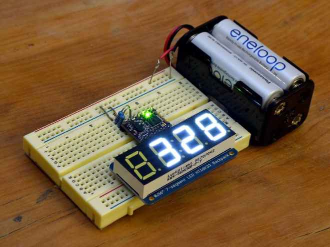
This project will show you how to create a standalone application with the MappyDot Plus working as an I2C master with an I2C 7 segment display. This example can also be adapted for use with a wide range of different client I2C devices for standalone applications.
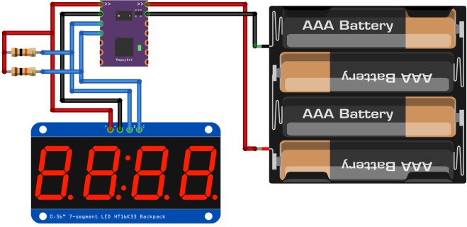
Once you have assembled the 7 segment display, you can now hook everything up as per the schematics below. Provided your battery supply outputs a voltage between 2.8 and 5 volts, you don’t need to use a voltage regulator to supply this project. Using 4xAA 1.2v rechargable NiMH batteries is perfect for this setup. If using 1.5V alkaline batteries, you should consider using a voltage regulator (or a diode with a large voltage drop) or opt for only 3xAA alkaline batteries.
Adafruit submitting OSHW certifications for boards

Exciting news from the Adafruit team, they have started the Open Source Hardware certification process for a bunch of their boards:
Adafruit submitting OSHW certifications for boards
Adafruit is an Open Source Hardware and Software company. To that end, Adafruit has begun working to submit many of their boards for certification by the Open Source Hardware Association. According to OSHWA:
“The certification program exists to make it easy for creators and users to identify hardware that follows the community definition of open source hardware maintained by OSHWA. Hardware projects that display the certification logo are licensed and documented in a way that makes it easy for users to use and build upon them.”
By registering their boards with OSHWA, Adafruit aims to ensure users that the products they sell are open-source, and easy to learn about.
Here are the boards that have recently been submitted:
CircuitPython Boards
- Adafruit Feather M0 Basic Proto
- Adafruit Feather M0 Adalogger
- Adafruit Metro M4
- Adafruit Feather M0 Express
- Adafruit Feather nRF52832 Bluefruit LE
- Adafruit Trinket M0
- Adafruit GEMMA M0
- Adafruit ItsyBitsy M0 Express
- Adafruit ItsyBitsy M4 Express
- Adafruit Feather M4 Express
- Adafruit HalloWing M0 Express
- Adafruit NeoTrellis M4 Mainboard
- Adafruit Metro M4 Express AirLift
- Adafruit Feather nRF52840 Express
- Adafruit Grand Central M4 Express
- Adafruit PyPortal
- Adafruit PyBadge
- Adafruit PyGamer
- Adafruit PyRuler
- Adafruit EdgeBadge
- Adafruit PyPortal Titano
- Adafruit PyPortal Pynt
- Adafruit ItsyBitsy nRF52840 Express
- Adafruit CLUE
- Adafruit Feather nRF52840 Sense
FeatherWings
- Adafruit FeatherWing OLED – 128×32 OLED Add-on For Feather
- Adalogger FeatherWing – RTC + SD Add-on For All Feather Boards
- DC Motor + Stepper FeatherWing Add-on For All Feather Boards
- 8-Channel PWM or Servo FeatherWing Add-on For All Feather Boards
- NeoPixel FeatherWing – 4×8 RGB LED Add-on For All Feather Boards
- Adafruit 4-Digit 7-Segment LED Matrix Display FeatherWing
- Adafruit 14-Segment Alphanumeric LED FeatherWing
- Adafruit Ultimate GPS FeatherWing
- Adafruit 15×7 CharliePlex LED Matrix FeatherWing
- TFT FeatherWing – 2.4″ 320×240 Touchscreen For All Feathers
- Adafruit Mini Color TFT with Joystick FeatherWing
- Adafruit CRICKIT FeatherWing for any Feather
- Adafruit AMG8833 IR Thermal Camera FeatherWing
- Adafruit INA219 FeatherWing
- Adafruit TFT FeatherWing – 3.5″ 480×320 Touchscreen for Feathers
- Adafruit Prop-Maker FeatherWing
- Adafruit 2.13″ Tri-Color eInk / ePaper Display FeatherWing
- Adafruit ADXL343 + ADT7410 Sensor FeatherWing
- Adafruit 2.13″ Monochrome eInk / ePaper Display FeatherWing
- Adafruit AirLift FeatherWing – ESP32 WiFi Co-Processor
Keep an eye out for more updates on this process.
Join two KiCad livestreams TODAY

At 9:00 AM US PDT today, April 1st, KiCad leader developer Seth Hillbrand will be hosting a KiCad Community meetup video conference on Jisti Meet:
Last week’s meetup was nice to see and talk with other KiCad users. Let’s do it again this week.
This week, I’m happy to answer questions and I’ll be working through designing a KiCad version of the Medtronic OpenVentilator project (http://www.medtronic.com/openventilator 5). You may have heard that Medtronic (a multi-billion $ company) bought the company that cancelled the original gov’t contract 2 for low-cost ventilators in 2015 and then this week released a “kind of” open source version 3 of their current (not low-cost) ventilator.
In reality, they released scans of the schematics and some word documents for bring-up procedures. I’m going to see if we can turn the scans into a set of useful KiCad schematics + board files. This still doesn’t get to what’s needed to actually recreate more of these ventilators but it is a needed first step.
If you are curious about recreating designs from incomplete schematics, reverse engineering in KiCad or just want to hang out and chat, please stop by.
Then at 12:00 PM US PDT, Piotr Esden will livestream KiCad board layout:
Electronics Let’s Play – iCEBreaker-bitsy update/design work Ep. 3

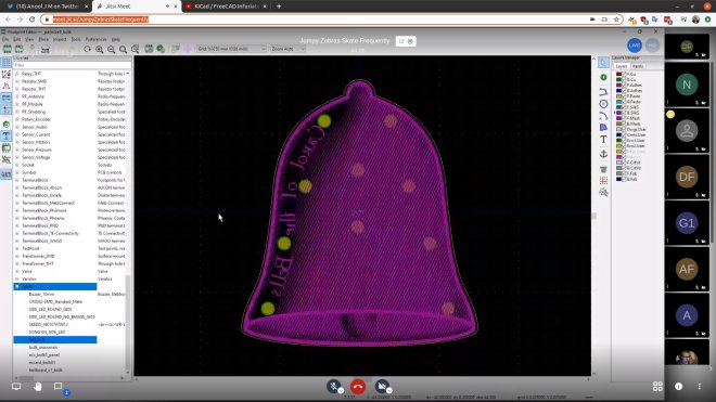
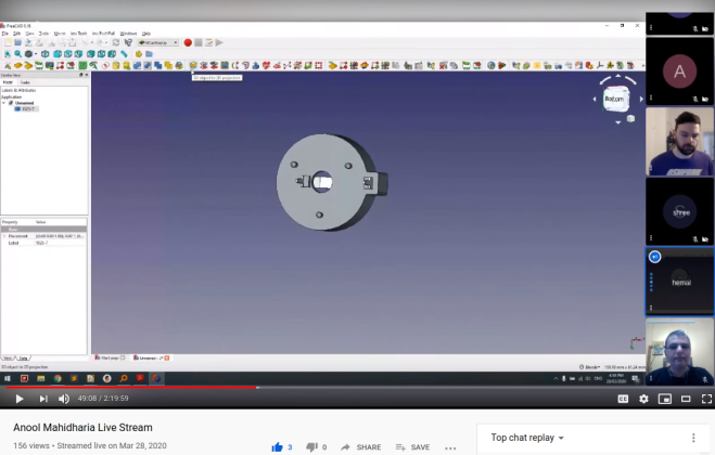
Use FreeCAD StepUp to verify KiCad footprints
Thanks to Hemal Chevli and Anool Mahidharia for showing how to make a 2D projection from a STEP model using the KiCad StepUp workbench in FreeCAD and then verify it against the footprint in KiCad!


Here is the record live stream:
Jump to around 48:00 to see this technique demonstrated:
Ricmohte: Ricoh digital camera using ESP32
The Ricoh GR II has a remote interface. But like most modern cameras the interface is terrible. It’s a WiFi Access Point that uses a web app. And because most modern phones are terrible, this means you have to juggle between WiFi that doesn’t provide an internet connection and a web app that kinda requires it. The Ricmohte uses the ESP32s WiFi to connect to the camera and issue commands.
There is a Ricmohte demo on YouTube:
