Flux Capacitor badge add-on

BTTF

We really like this “Back to the Future”-themed Flux Capacitor badge add-on (SAO) by Squaro Engineering made with our “After Dark” service (which features clear soldermask on black fiberglass substrate).

Checkout the GitHub repo for more: sqfmi/BTTF-BADGE

The board is also available an OSH Park shared project
Order from OSH Park

Flux Capacitor badge add-on

iCE40 FPGA Board for the Raspberry Pi

Matthew Venn has created a FPGA dev board based on Lattice iCE40 8k for the Raspberry Pi.  The board uses our After Dark service which features clear solder mask on a black substrate:

board

FPGA dev board based on Lattice iCE40 8k

Aim

  • Make my first PCB with an FPGA
  • Keep it super simple and cheap
  • Configured by on-board FLASH or direct with a Raspberry Pi
  • 6 PMODs, 2 buttons, 2 LEDs, FLASH for configuration bitstreams.

What a Lattice iCE40 FPGA needs

  • A clock input. Has to be provided by an oscillator, it doesn’t have a crystal driver.
  • 1.2v core supply for the internal logic.
  • 2.5v non volatile memory supply. Can be provided via a voltage drop over a diode from 3.3v.
  • IO supply for the IO pins, different banks of IO can have different supplies. This design uses 3.3v for all banks.
  • Get configured over SPI interface. This can be done directly by a microcontroller or a computer, or the bitstream can be programmed into some FLASH, and the FPGA will read it at boot. If FLASH isn’t provided then the bitstream needs to be programmed at every power up or configuration reset.
  • Decoupling capacitors for each IO bank.

PCB

BOM

  • FPGA iCE40-HX4K-TQ144 (8k accessible with Icestorm tools)
  • 3.3v reg TLV73333PDBVT
  • 1.2v reg TLV73312PDBVT
  • 12MHz oscillator SIT2001BI-S2-33E-12.000000G
  • 16MB FLASH IS25LP016D-JBLE (optional).

Test

See the test program. This makes a nice pulsing effect on LED2, and LED1 is the slow PWM clock. The buttons increase or decrease pulsing speed.

make prog

Yosys and NextPNR are used to create the bitstream and then it’s copied to the Raspberry Pi specified by PI_ADDR in the Makefile.

Fomu-Flash is used to flash the SPI memory, or program the FPGA directly.


iCE40 FPGA Board for the Raspberry Pi

“No knobs! No 555s! No reason whatsoever!”

Here’s a #badgelife project from Sam Ettinger on Hackaday.io:
EVO_Vn_UwAA_eAt

This is a shitty add-on with one RGB LED controlled by twelve switches. The top row controls the red brightness, the middle row controls the green brightness, the bottom row the blue brightness. Each row of switches is like a 4-bit binary number, giving 16 brightness options for each color channel.

Should I have used knobs instead of switches? Maybe, but then it’s not a shitty add-on, is it?

Each color channel is controlled by its own ATtiny10, reading an analog voltage and PWMing the LED accordingly. The ATtiny10s are programmed using [Simon Merrett]’s SOICbite footprint, which I *love*.

Should I have used a 555 instead of a microcontroller? Perhaps. But isn’t this a better solution for a shitty add-on?

“No knobs! No 555s! No reason whatsoever!”

Goodies for the Open Hardware Summit

The Open Hardware Summit is next week, March 13th!

Here’s a sneak peak at one of the items that everyone will receive in their conference goodie bags:

image001-2

Thanks so much to Kevin Walseth at Digi-Key for making it happen! ⚡️

And thanks to our Dan (@tekdemo) for the beautiful “After Dark” PCB art  🦋

ESa3vAFWAAA-4a5

Thanks to Chris Gammellfor the “Getting to Blinky” videos! 🎥  It is a great way to learn KiCad:
Screenshot from 2020-03-06 11-38-24
Thanks to Kyle at Digi-Key for showing what that board looks like in action!
Screenshot from 2020-03-06 12-33-11
I made the curved traces with the “Rounder for Tracks” KiCad plugin from the RF-tools repo:
Here is the GitHub repo with the KiCad design files: pdp7/gtb
If you can’t make it to the Open Hardware Summit, then the design is also available an OSH Park shared project:
Screenshot from 2020-03-06 12-06-23
Note: after adding the board to the cart, please click on the “After Dark (Black Substrate + Clear Mask)” option
Follow me on Twitter for updates on the Open Hardware Summit:

Goodies for the Open Hardware Summit

RC2014 Homebrew Z80 Computer Kit… now in After Dark!

The RC2014 is a Z80 based modular homebrew.  The designer Spencer Owen recently did a version with our After Dark service (clear solder mask on black substrate) and it is available on Tindie:

EN7DKhoWoAAqhXS

Special edition Z80 based retro computer kit with stunning After Dark PCB

Fundamentally, this is an RC2014 Mini. A single board Z80 computer that runs BASIC or Z80 assembly code. If you are looking for an easy to build, good looking, well supported Z80 single-board computer, you probably should just go and buy a RC2014 Mini

However, if you are after a stunning looking Z80 single board computer which is one of only 25 in the world, then read on…

EN7DKtIWkAALFCL

Limited Edition RC2014 Mini After Dark

  • Amazingly beautiful AfterDark PCB from OSHPark features black FR4 substrate, 1oz copper with clear solder resist, ENIG (gold) pads and white silkscreen
  • Every track from the original RC2014 Mini has been relaid for maximum visual appeal
  • RC2014 logo in the top copper layer
  • Turned pin chip sockets
  • White connectors, jumpers and reset switch to compliment the silkscreen
  • Laser-cut mirrored base plate with brass PCB standoffs allow the underside of the board to be seen
  • Rubber mounting feet
  • Limited run of 25 kits, with each one being numbered. Kits will be supplied strictly in number order and records kept if later verification is required
  • Option to buy a standard RC2014 Mini with a 50% discount so you can hack around and modify the standard RC2014 Mini whilst leaving the Limited Edition RC2014 Mini After Dark kit intact. Or mix & match the black and white connectors to create your own unique RC2014.
  • Same specification as standard RC2014 Mini (Z80 processor at 7.3728MHz, 32k RAM, ROM with Microsoft BASIC / SCM Monitor, 5v power over USB barrel jack cable or FTDI cable, 115,200 baud serial communication, keyboard connector for Universal Micro Keyboard, Pi Zero header option for Pi Zero Serial Terminal
  • Luxury packaging for that unique “unboxing experience”
  • Shipping will automatically be upgraded to signed, tracked or recorded delivery based on your location
  • Limited run RC2014 After Dark stickers

EN7DK2zX0AAl7vx

RC2014 Homebrew Z80 Computer Kit… now in After Dark!

Low Power ESP32 Handheld

Max.K on Hackaday.io has created a pocket sized ESP32 display board with 300µW Always On Display:

7327171577179362033.jpeg

Low Power ESP32 Handheld

This handheld board is powered by an ESP32 and features a transflective Sharp memory LCD.  Similar to my previous Chronio smartwatch the focus of this project is on low power consumption.  Using the ESP32’s ULP core, the board can go into deep sleep with an active display.   The software includes a menu interface with a simple RSS reader.

Some of the key features are:
– 400x240px 2.7″ SHARP memory display
– 350 mAh LiPo battery with USB charging
– Always On Display with 300 µW power consumption
– 4-way joystick and buttons
– Date and time using built in RTC with NTP sync
– RSS Feed / Website parser

Layout files and Code on GitHub: https://github.com/CoretechR/ESP32-Handheld


Low Power ESP32 Handheld

DIY EEPROM Programmer

Erik van Zijst writes about designing a DIY EEPROM Programmer:

0_IyM1A_fdNrr3KZdr

To load data you need an EEPROM programmer and like the chips, these devices have become somewhat rare and expensive. Hence the project to build one ourselves.

The easiest approach is probably to use a microcontroller to bridge between the chip and a computer, run a bidirectional serial protocol between the microcontoller and the computer to send image data back and forth.

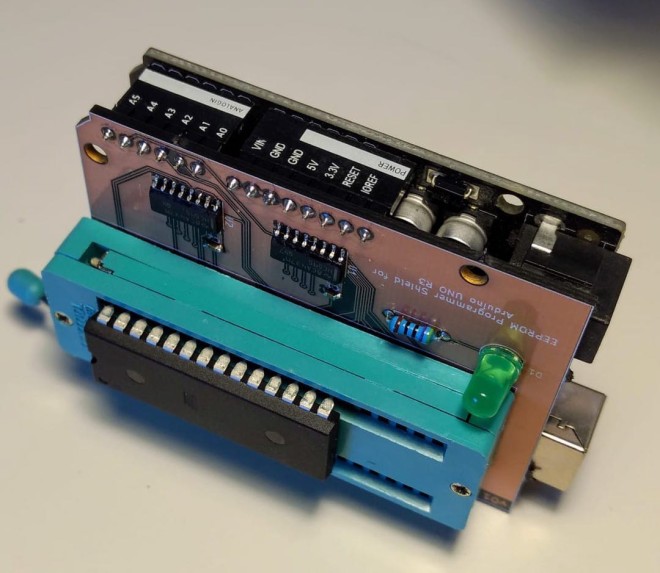
Since the AT28C256 requires 5v for writing, we can’t use a Raspberry Pi or Arduino Nano/Mini as their GPIO ports are all 3.3v. The regular old Arduino UNO is 5v though and so should work nicely.

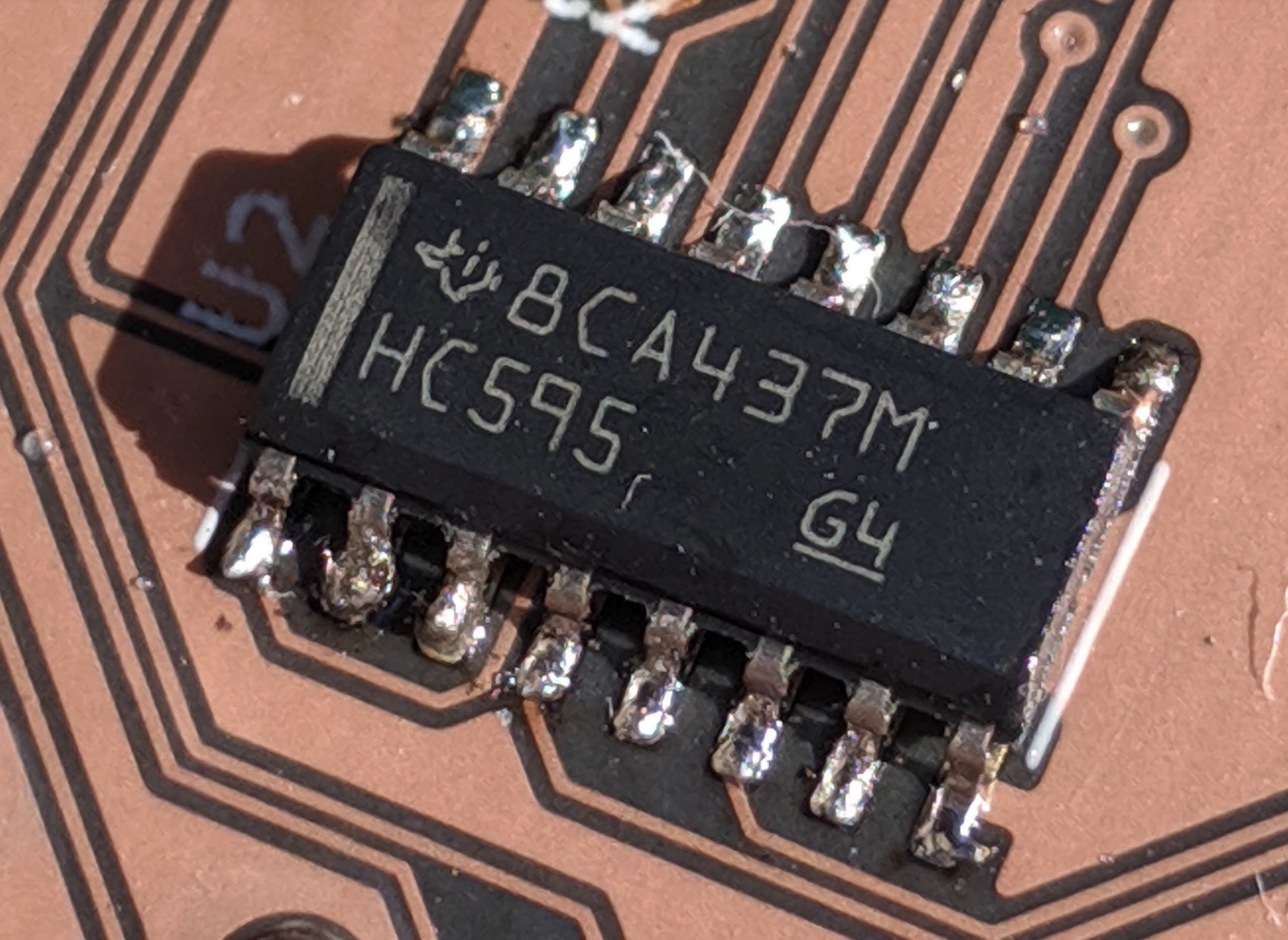
To gain some experience hand-soldering surface mount devices, I picked SMT packages for the shift registers and decoupling capacitors.

The ZIF socket is a 40 pin device I had lying around. Since the AT28C256 is a 28-DIP, I just left the 12 left-most pins unconnected. It’s a low budget project.

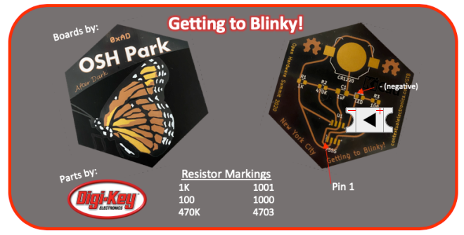
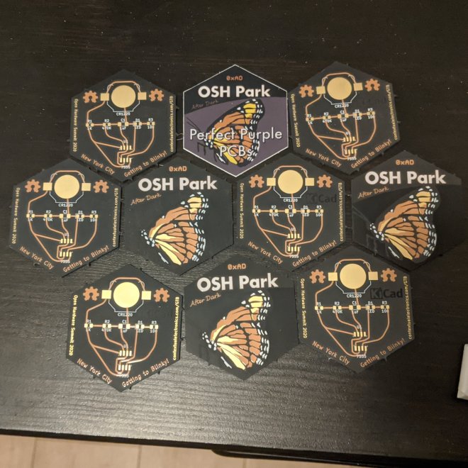
When I went to upload the Gerber files to OshPark for fabrication I noticed their “ After Dark “ option that uses a black FR4 substrate, with transparent soldermask that makes the copper traces pop against a black background.

The KiCad project as well as the serial protocol description and code for the Arduino and Python CLI can be found on on GitHub.

DIY EEPROM Programmer