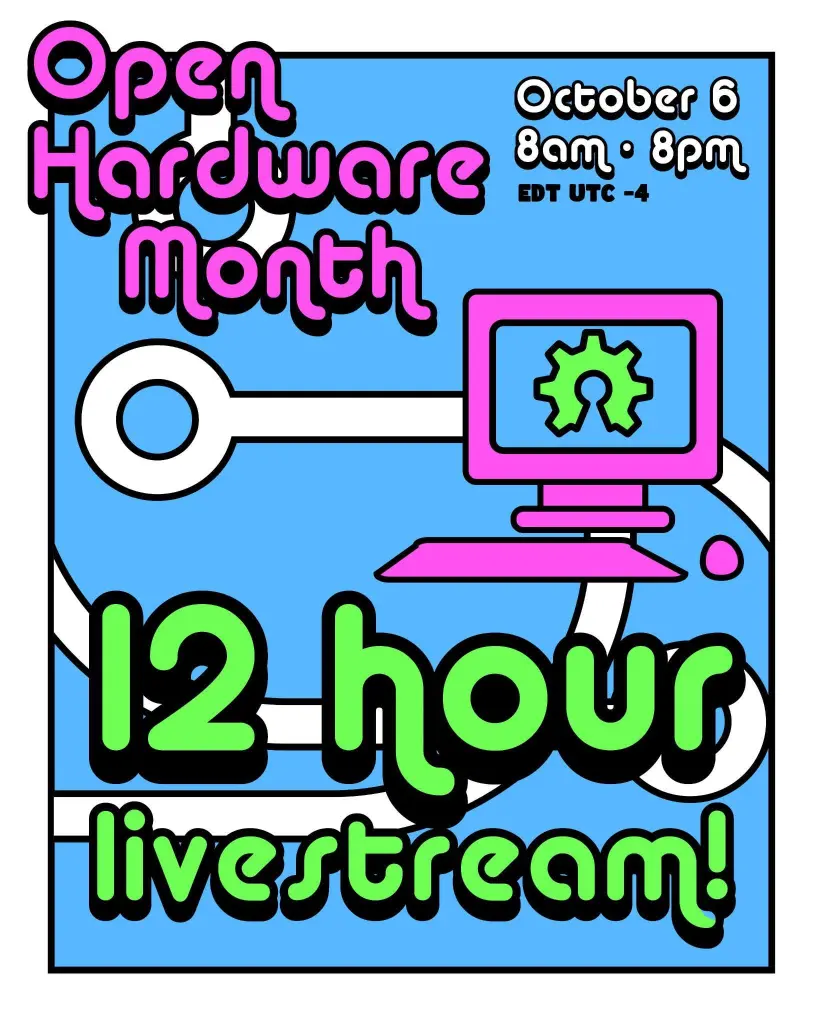
Join OSHWA for 12 full hours of exciting and fascinating open source hardware with creators from all over joining us to show off their work!
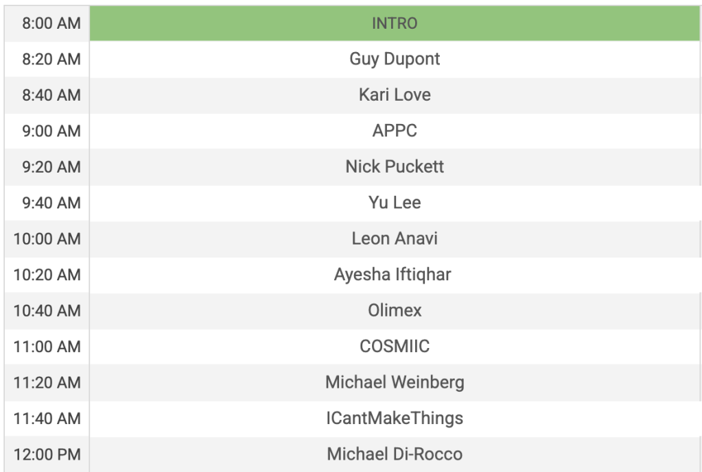
Find out more on the OSHWA blog…

Join OSHWA for 12 full hours of exciting and fascinating open source hardware with creators from all over joining us to show off their work!
Find out more on the OSHWA blog…
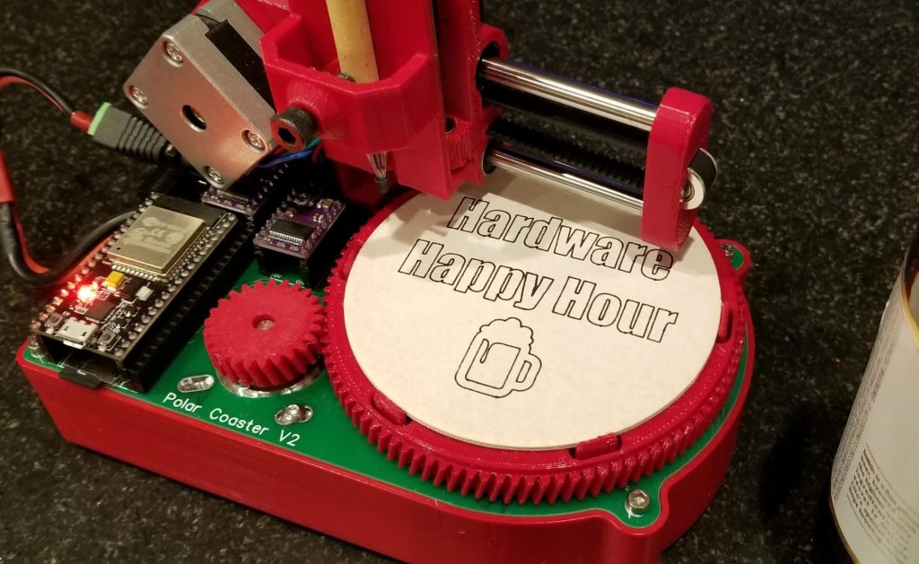
Hey Portland! Hardware Happy Hour is tonight, February 18th, at the Bye and Bye on Alberta. It’s an informal way to socialize, show off your projects, and talk about the world of hardware. From beginner to expert, all are welcome!

Can’t make it tonight? It’s a monthly a event so signup to the meetup page to find out about the next one.
Don’t live in the Portland area? There are Hardware Happy Hours in other cities, too:
There is also a Discord server for people interested in organizing Hardware Happy Hours in their cities.
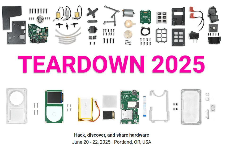
Teardown is amazing annual June event in Portland for hacking, discovering, and sharing hardware. The call for proposals closes on Wednesday, January 15th:
Teardown 2025 is a great opportunity to spread your ideas, show off your work, solicit feedback, enrich the hardware community, and foster collaborations. Previous events have featured amazing talks and workshops on a wide range of hardware topics — FPGAs, DIY AI, KiCad, firmware, BOMs, covert blinkenlights, the DMCA, security, RISC-V, prototyping, and so much more. Installations and demonstrations have included circuit sculptures, modular synths, DIY satellite receivers, retro gaming computers, robotic arms, and electronic jewelry.
Would you like to participate? There are four general session formats:
- Talk: 25 or 50 minutes
- Workshop: the standard workshop slot is 80 minutes, hands on
- Demo: show off your project in one of the common areas, attended
- Installation: display your creation in one of the common areas, unattended
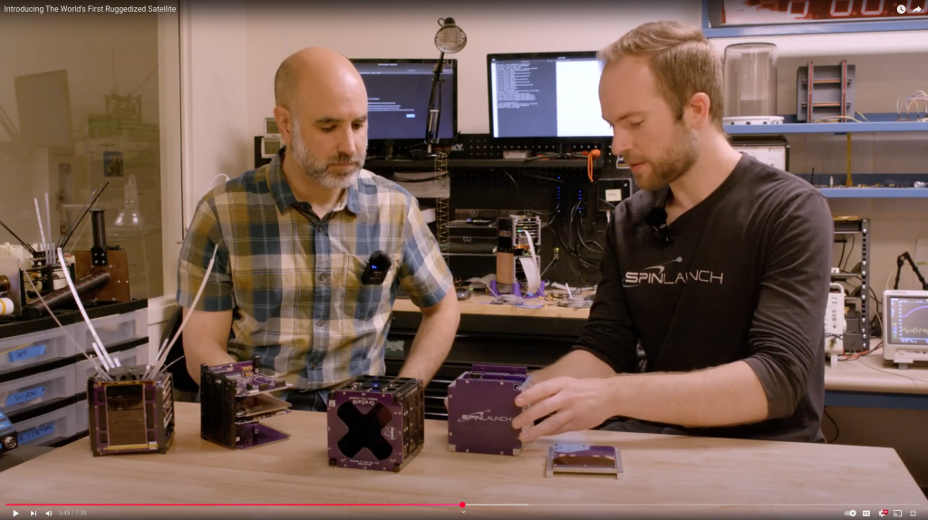
We were excited to see our friends at the Portland State Aerospace Society (PSAS) team up with SpinLaunch to test the limits of OreSat:
Introducing The World’s First Ruggedized Satellite
Think satellites are too fragile to survive high-g environments? Think again. We’re excited to unveil our latest ruggedization milestone: spinning a Portland State University satellite to 10,000Gs! Partnering with Portland State’s satellite program, OreSat, we demonstrate the feasibility and process of ruggedizing off-the-shelf spacecraft. Learn how strategic design tweaks and a shift of engineering intuition pushed an existing satellite over the finish line, ready to be launched with SpinLaunch’s revolutionary technology.
Allison Parrish wrote a detailed blog post about their Game Boy mod journey:
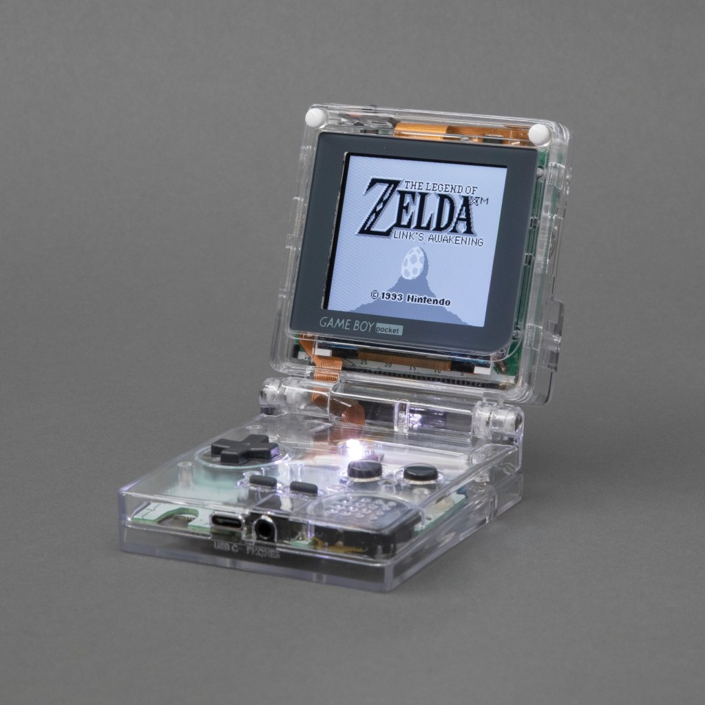
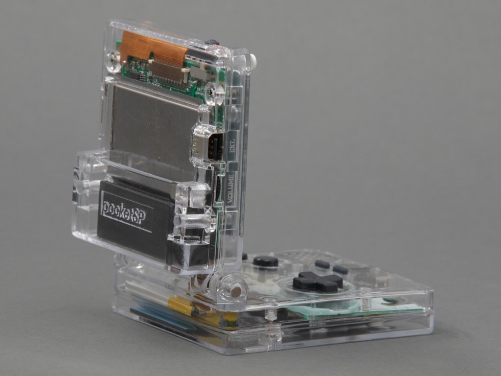
When to hold ’em and when to fold ’em: Adding a hinge to a Game Boy that God never intended
Over the summer I dug in deep with Game Boy modding and made this: the Game Boy Pocket SP. It’s a Game Boy Pocket motherboard that I cut in half and then put into a custom-designed shell with a hinge, a la the Game Boy Advance SP. The build has a pair of custom-designed flex PCBs to make routing signals between the two halves of the board easier. Along the way I taught myself CAD (with FreeCAD), PCB design (with KiCad) and 3D printing. The 3D models and PCB layouts for the Pocket SP are available on GitHub. In this post, I’m going to talk about why and how I made the Pocket SP, and how you can make your own.
The design of a flexible PCB ribbon cable was key to the ability for the mod to fold up:
I designed a pair of flex PCBs that could be soldered directly to the board. One of the flex PCBs would end in a thin ribbon, which would go through the hinge assembly, and then connect to the other PCB with an FPC connector. This would make it easy to assemble and disassemble the unit, and would also make soldering pretty easy.
I think the closest I’d ever come to designing my own PCB was in grad school, when I downloaded EAGLE and never opened it and then deleted it at the end of the semester. But I’ve always wanted to design and fabricate my own PCB! I decided to use KiCad, because it’s free and open source and also the tool of choice for many modders in the community that I respect.
As with FreeCAD, the tutorial material for KiCad is pretty great. I spent an afternoon following along with the Getting Started guide and felt confident enough afterwards to actually start making my board. My schematic is pretty simple, since all I’m doing is connecting pads to headers and connectors.

Greg Steiert created an USB Blaster alternative which makes it possible to drag-n-drop an image onto an Altera FPGA:
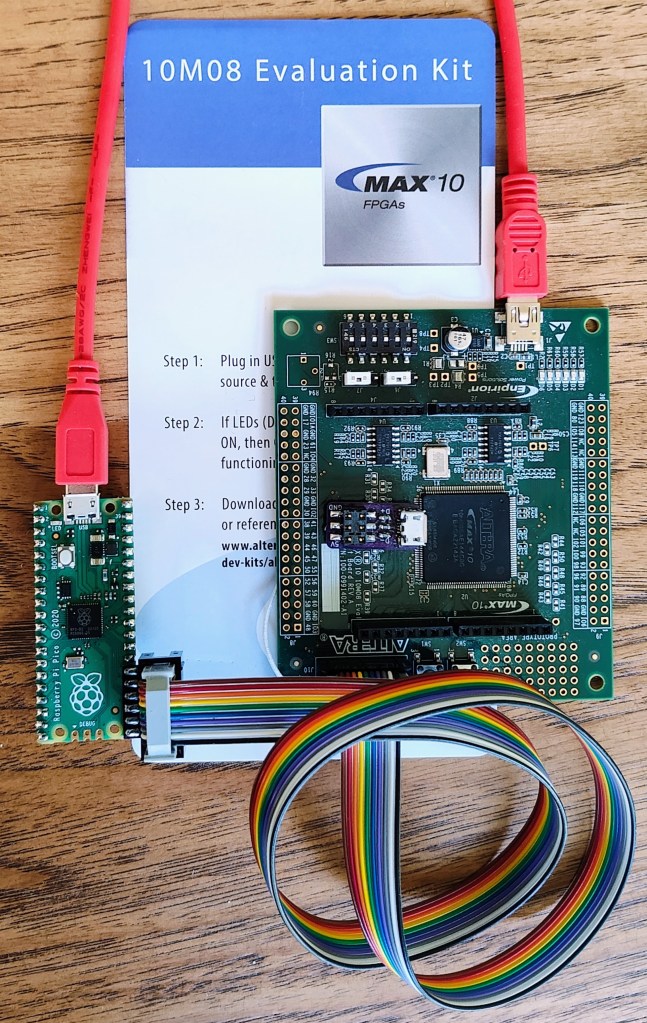
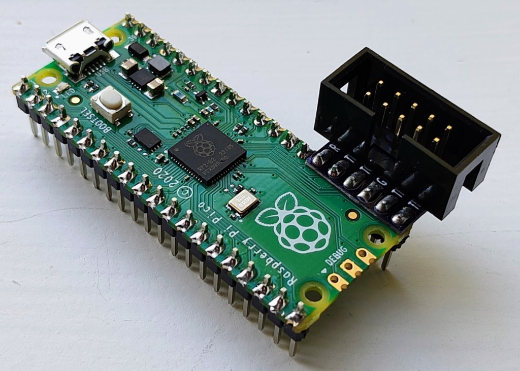
This project has taken many detours, often due to a lack of time for software development (or my preference for circuit-board design). In any case the latest detour came when I learned about the PICO-DIRTYJTAG project by Patrick Dussud. This project enables the $4 Raspberry Pi RP2040 Pico board to work with openFPGALoader to program a wide variety of FPGAs. This would save me quite a bit of time with software development, or so I thought.
Getting PICO-DIRTYJTAG working with openFPGALoader was a breeze. My first test was to load an image into the MAX10 10M08 Evaluation Kit that does not include an integrated loader. openFPGALoader “supports” MAX10 through SVF files, which technically works, but is painfully slow. So slow that I decided to find a better software solution. I had stalled on my previous efforts to implement an SVF interpreter and decided to look for some other options. Altera also provides STAPL JAM and JBC files for programming, and these are a little more embedded friendly. JBC files convert JAM files to byte code and are more space efficient, so I opted to implement a JBC loader.
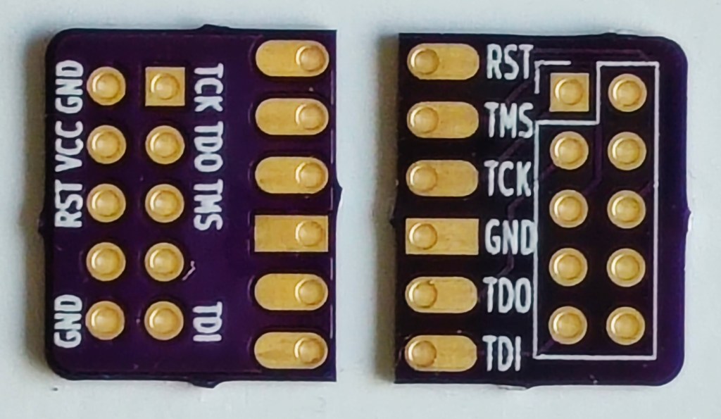
This new combined UF2 file can be drag-n-dropped onto the Pico board and will immediately program the FPGA through the pico-dirty-blaster adapter. The pico-jbi.uf2 JBC player firmware and the uf2jbc.py generator script are available at the pico-dirty-blaster github repo.
We’ve been excitedly following Aleksa Bjelogrlic’s open source hardware high-performance oscilloscope project and are very happy to see it has already shot way past its funding goal on Crowd Supply:
A new type of oscilloscope that’s fast, flexible, and completely open
ThunderScope packs the power of expensive, bulky high-end oscilloscopes into a portable and affordable package. While traditional scopes are limited by their built-in processing capabilities and cramped user interfaces, ThunderScope is designed to stream the complete 1 GS/s of sample data in real time to your computer for processing and analysis. ThunderScope’s fast connections (via Thunderbolt, USB 4, and PCI Express) and unique software-defined architecture allows it to be used for everything from simple measurements to complex protocol analysis.

ThunderScope is a re-imagining of how test equipment is designed and used. The hardware focuses on the most important aspect of an oscilloscope – the analog frontend. Traditional scopes have to split their budget between the analog frontend and support components such as a small screen, underpowered microprocessor, and large chassis. ThunderScope takes a different approach: A no-compromises analog frontend that connects to your computer over the fastest available interfaces. Unlike any other scope that handles processing on device, this change in approach allows ThunderScope to use your computer to its fullest potential. This makes ThunderScope the only scope that will get better every time you upgrade your computer.

In this episode of the Teardown Sessions, Crowd Supply’s Helen Leigh celebrates the launch of the Thunderscope oscilloscope with Aleksa Bjelogrlic:
James Wilson writes about making an open source high frequency oscilloscope probe:
Students, hobbyists, and professionals today enjoy unprecedented access to powerful and affordable test equipment for understanding and building electronic projects. But as enthusiast projects have become more advanced and ambitious, it is still possible to hit the limits of entry-level equipment. I have been excited about open source hardware as an avenue to advance the performance and accessibility of test equipment, in much the same way the early open source software focused on development tools as a foundation for greater access to computing. This article is about my experiences building an open hardware single-ended active probe.
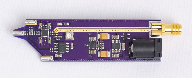
Active probes shine with high-frequency circuits or ones that require low loading, because their input capacitance is smaller by an order of magnitude. The operating principle behind an active probe is to use a buffer amplifier that has high input impedance and reproduces the signal at lower output impedance.
A project is now underway to build an open source oscilloscope using this chip in the front end, and I’ve been experimenting with a complementary effort to build a single-ended active probe, with the following design goals:
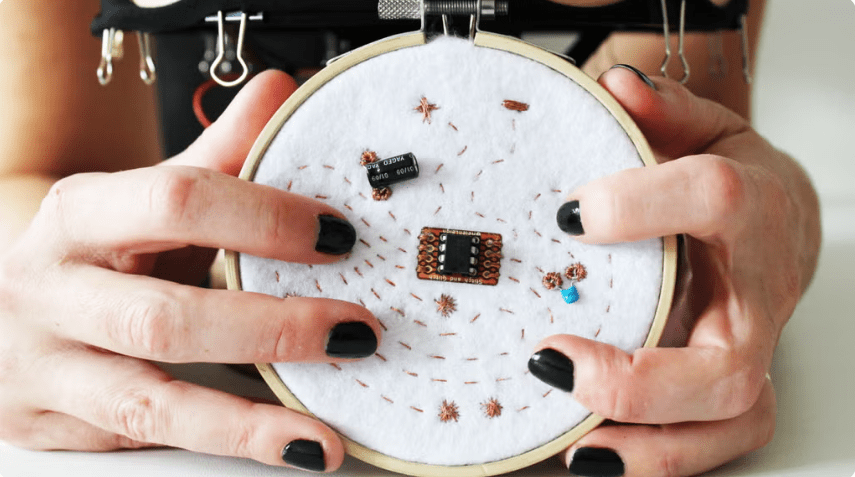
Greg Steiert has added sound to his amazing NFC business card:
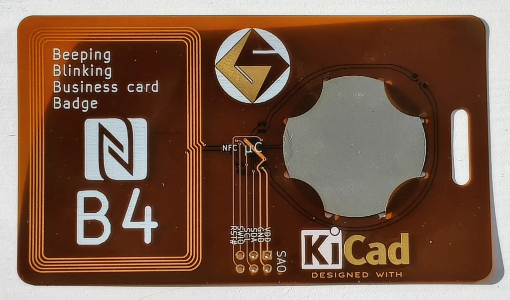
Beeping, Blinking Business-card Badge (B4)
This 1mm thick, environmentally friendly, re-usable business card delivers a vcard with a tap and actively indicates the access with audio and visual cues. Everything is powered from the energy harvested through NFC so there are no batteries to replace. The card provides a URL to a vcard. This is a great project for OSHPARK’s Flex service.
This video shows the 1mm thin Beeping Blinking Business card Badge playing a tune while being read:
This project has evolved over the years. The current design consists of the NXP NTAG I2C Plus NFC EEPROM that supports energy harvesting. The NTAG device powers a WCH CH32V003 MCU that drives the buzzer and LED(s). There are three implementations of this circuit:
b4thin: 1mm thin flex-circuit design
b4handy: a full size hand solderable design
nfcwchsao a compact pocketable design
I’ve tried to document my learnings along the way, including designing a battle board to see which NFC EEPROM provides the most current. These insights are provided in the project logs.
These designs are ideal for OSH Park’s board service. OSH Park provides 3 copies of the design so you get three attempts to assemble your custom business card. Sometimes, I made use of all three. The KiCad files are available on github so you can customize them yourself and build your own personalized card. With the current three versions of the design there is something for every skill level. Think twice about the 1mm thin design if you don’t have access to a hot plate or heat gun to mount the thin leadless packages
Ready to test your soldering skills?
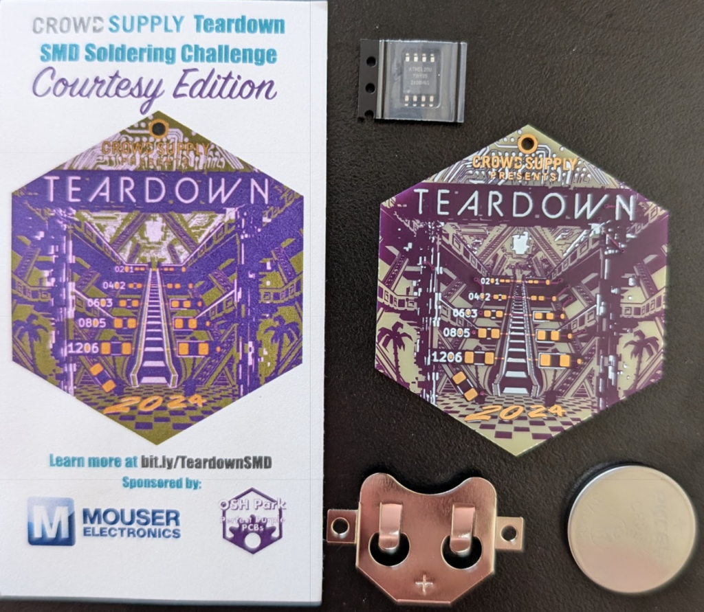
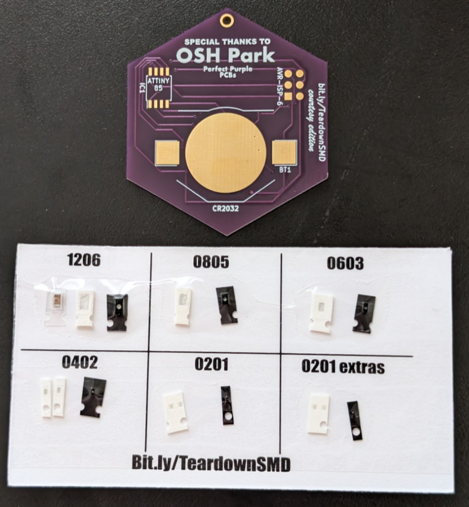
Teardown 2024 begins today in Portland and Darcy has designed and kitted an exciting SMD soldering challenge!
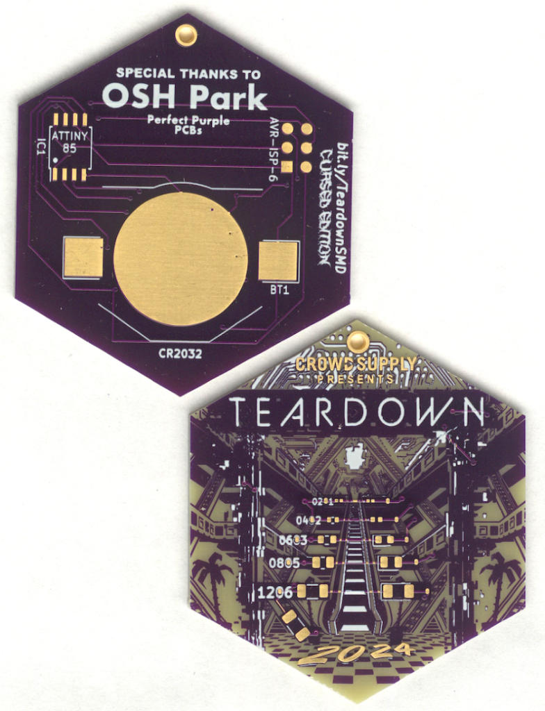
Teardown SMD Soldering Challenge! (Round One)
June 21, 2024 12:00-12:50 PM
Put your surface mount soldering skills to the ultimate test! Begin with the manageable 1206 package and take on increasingly tiny components, each step pushing your abilities further. This SMD project is powered by a CR2032 coin cell and an Attiny85 SOIC, offering a perfect blend of challenge and excitement. Brace yourself for the ultimate trial: hand soldering a 0201 package, a feat so intricate it will have you questioning your sanity. Are you ready to show off your skills and conquer this soldering adventure?
Teardown SMD Soldering Challenge! (Round Two)
June 23, 2024 2:00-2:50 PM
Put your surface mount soldering skills to the ultimate test with this gorgeous Teardown-themed SMD Challenge board! Begin with the manageable 1206 package and take on increasingly tiny components, each step pushing your abilities further. This SMD project is powered by a CR2032 coin cell and an Attiny85 SOIC, offering a perfect blend of challenge and excitement. Brace yourself for the ultimate trial: hand soldering a 0201 package, a feat so intricate it will have you questioning your sanity. Are you ready to show off your skills and conquer this soldering adventure?
This workshop is first come first serve, limited to 20.