2020 Hackaday Prize Reveals Four Open Challenges and New Dream Team Program


The 2020 Hackaday Prize begins right now. Our global engineering challenge seeks solutions to real-world problems. If you like to come up with creative solutions to tough problems, four non-profits can use your help. We need hackers, designers, and engineers throughout the world to work on designs for conservation, disaster relief, renewable resources, and assistive devices.

via 2020 Hackaday Prize Reveals Four Open Challenges and New Dream Team Program — Hackaday

Quote

Hackspace column on PCB design

My recent Hackspace magazine column is an introduction to printed circuit boards (PCBs) and how they can improve DIY projects:

PcB

PCB love – making circuit boards

You made your first LED blink, you learned how to use a breadboard, and you know which end of the soldering iron to hold. So what’s next? High up on the list of essential electronics skills is learning how to design and make your own printed circuit board (PCB). My first PCB was a POV (persistence of vision) display, a modified version of an Adafruit open hardware design. I still remember how exciting it felt to open up my mail and solder a board I designed myself!

A PCB is a board with traces (lines) that connect different pads or holes for electronic components to each other, or to connectors that allow us to hook up power, microcontrollers, or other parts. We use solder to connect the pads or holes on the bare board to the component that the board was designed for. Once the components are in place, the traces let us push power or data around our boards.

Screenshot from 2020-05-21 14-23-56

PCBs themselves are like a sandwich made up of layers of different materials. The main ‘body’ of a PCB is made of some kind of substrate; typically a fibreglass called FR4. On top of that is a thin layer of copper-foil that lays out the traces and pads, then a layer of coloured solder mask which prevents solder from sticking where it shouldn’t.

This solder mask is often green, but you can get all sorts of colours, such as my favourite – purple. The copper that is not covered by solder mask then gets protected by a surface finish such as HASL (solder) or ENIG (gold plating). Finally, there is the silkscreen layer where text and symbols are printed.

Like any good sandwich, you can keep adding in more layers of copper, from two layers up to tens of layers. It’s also worth knowing that rigid fibreglass isn’t your only option: you can choose a material called Kapon (polyimide film) to make flexible PCBs. You can even make your PCB sandwich using both fibreglass and Kapon to make a board that is flexible in some places and rigid in others. One super-cool option, that both OSH Park and Evil Mad Scientist Laboratories have been using recently, is black fibreglass paired with a clear solder mask, so all your copper traces are visible.

In next month’s column, I’ll be talking about the awesome ways the hardware hacker community has been using PCB design to make cool electronics projects and beautiful art, as well as sharing some of the tools they’re using to make their boards. In the meantime, I recommend this excellent video that visualises the composition of a PCB: hsmag.cc/SI2m31 (How do PCBs Work?  by Branch Education).

Hackspace column on PCB design

Breakout board for 8×12 analog cross-point switch

J. Ian Lindsay of  Manuvr Breakouts has designed this breakout board for Analog Devices’ 8×12 analog cross-point switch:

2019-12-01T08_58_25.068Z-IMG_20191201_013632

ADG2128 Breakout

The ADG2128 is an incredibly flexible cross-point switch. It supports 5/-5v, 3.4MHz i2c, and is unrestricted as to its connectivity options between its rows and columns.

This is a high-dollar part, and I’ve been designing with it for more than 5 years. So I polished my breakout board to reuse them during a project’s prototyping phase.

This board has decoupling capacitors adequate to handle the whole analog voltage range, i2c address selection jumpers, and differentiated ground layers for noise isolation or differential operation below 0v, according to the project’s demands.


Breakout board for 8×12 analog cross-point switch

BreadboardBuddy Pro

BreadboardBuddy Pro from AtomSoftTech on Tindie:

2015-01-25T14_12_11.357Z-Clipboard01

What is the Breadboard Buddy Pro

The BBBPro is a 4 in 1 breadboard tool. The amount of time you save using this is crazy! Ive been using my original Breadboard Buddy for years and the main addition is the newer CP2104 and Lipo Charging.

The board can be broken down into four main parts.

USB Power, USB 2 UART, LIPO Charger, Reset Button.

USB Power

Using a MicroUSB cable you can supply the board with its power. The board can output 5v and 3.3v simultaneously. Using the Jumpers on each of the top corners you can select which supply goes to which rail on breadboard.

If using a battery please note that there will obviously be no 5v supply. You can take 4.2 (or what ever the voltage on battery may be) from the BATT pin. Otherwise it will supply power to the 3.3v regulator and you can still use that on the power rails.

USB 2 UART

The USB to UART uses the CP2104, its a beautiful less expensive part than the FT232RL. It has a RX and TX led for indication of data transmission and reception. Supports 5/6/7/8 Data bits, Stop Bits 1/1.5/2, Parity odd/even/mark/space/none, Baud Rates 300bps to 2Mbits. Has a 576 transmit and receive buffer.

Lipo Charger

Uses the widely known and trusted MCP73831 for lipo charging. These ICs are so popular and tested so much that it almost guarantees your battery will be charged safely. The same charging circuit is used by other suppliers of similar circuits. What makes mines special is the ability to still supply power to circuit while charging, without crossing the voltage. Has a option for 100mA or 500mA charging on bottom. (Solder Jumper)

Reset Button

Just about any breadboard user knows how important a reset button can be. Using DIP MCUs are awesome for prototyping but all these extra components can take up so much space. This button isnt taking any space away. Also its pull up to 3.3v or 5v so you MCU is safe. (please ensure you select correct voltage on solder jumper on bottom) Can be used as a General Purpose pulled up button as well.

BreadboardBuddy Pro

KiCad 5.1.6 released

Screenshot from 2020-05-16 21-51-10

KiCad 5.1.6 has been released:

The KiCad project is proud to announce the latest series 5 stable release. The 5.1.6 stable version contains critical bug fixes and other minor improvements since the 5.1.5 release. It also includes improved footprint, symbol, and 3D model libraries, translations, and documentation.

This is also the first stable point release made since switching to gitlab for main kicad source code hosting.

A list of all of the fixed bugs since the 5.1.5 release can be found on the KiCad 5.1.6 milestone page. This release contains several critical bug fixes so please consider upgrading as soon as possible.

Read more…

KiCad 5.1.6 released

Flux Capacitor badge add-on

BTTF

We really like this “Back to the Future”-themed Flux Capacitor badge add-on (SAO) by Squaro Engineering made with our “After Dark” service (which features clear soldermask on black fiberglass substrate).

Checkout the GitHub repo for more: sqfmi/BTTF-BADGE

The board is also available an OSH Park shared project
Order from OSH Park

Flux Capacitor badge add-on

STM32L4-based RF-to-USB dongle

Philip Salmony has designed a STM32L4-based RF-to-USB dongle using a low-power NRF24 2.4GHz transceiver:

687474703a2f2f7068696c73616c2e636f2e756b2f77702d636f6e74656e742f75706c6f6164732f323032302f30352f535452462d33442e706e67

KiCad STM32 + RF + USB Hardware Design

Overview of STM32, RF, and USB hardware design, schematic creation, and PCB layout and routing in KiCad using a real-world example project. (Timestamps in description) Various tips on controlled impedance routing, differential pairs, USB, and RF layout. Correction in schematic: NRF24 IREF pin needs to be pulled low to GND via a 10k resistor (not to 3V3 as shown in the video!). Fix has been pushed to GitHub.

STM32L4-based RF-to-USB dongle

Open Source Hardware Certifications for April 2020

From Make magazine:

Open Source Hardware Certifications for April 2020

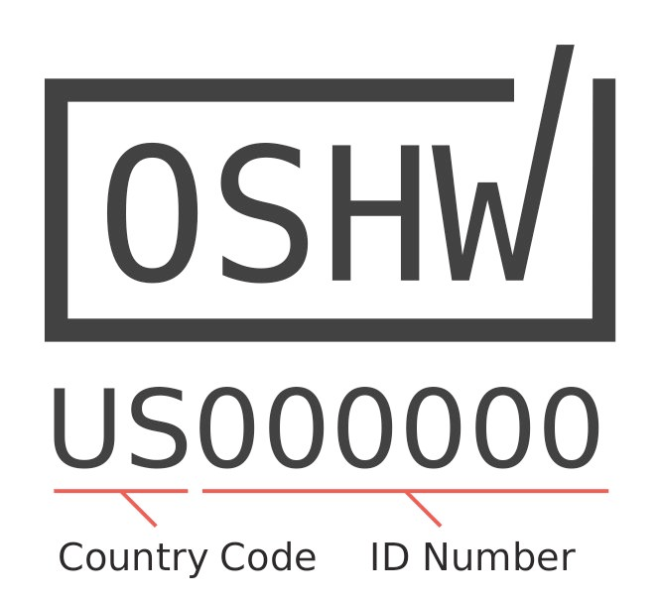
The Open Source Hardware Association (OSHWA) runs a free program that allows creators to certify that their hardware complies with the community definition of open source hardware.  Whenever you see the certification logo, you know that the certified hardware meets this standard.

apr-oshw-00

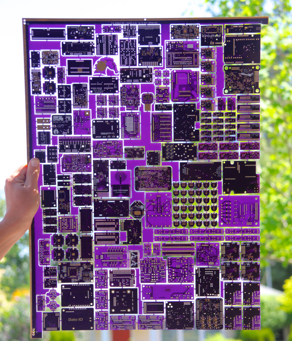
The certification site includes a full list of all of the certified open source hardware. Here is all of the hardware that was certified in April, which comes from the United States, Azerbaijan, India, Croatia, Germany, Poland, and Spain.

The OSHW community had been off to a strong start in 2020 with 54 projects certified in Q1. After February, we predicted here on Makezine.com that the certification program was on track for its strongest year ever. The surge in April has far surpassed our expectations with a total of 269 total projects certified last month alone, nearly twice that of 2019 in just one month.

Adafruit (All The Things)

Open Hardware leader Adafruit has dedicated a massive amount of time and effort towards certifying their back catalog of products. Hundreds have already passed certification at the time of writing this. We colloquially dubbed last month “Adafruit April” because of the sheer number of projects. In an interview with OSHdata, Founder Limor Fried takes us behind the scenes:

“Adafruit had certified some boards in the past to help support the effort. The barrier for certification for us was time. For us, the question was – do we stop everything and try to certify hundreds of boards? Or do we keep making open-source hardware? We choose to keep making open-source hardware with a goal to get it certified eventually, and/or wait for an API to automate the certification,” Fried explains.

Then COVID-19 happened. Adafruit has been running for 60+ days with no illnesses, no layoffs, no furlough, and no cut hours. They continued operations (after being deemed an essential business in NYC by Executive Order 202.6). Despite being busier than ever, this was also a time for reflection.

“It did occur to us that while our hardware is and always will be open-source, it was not certified. In March with the death rate increasing each day, as grim as it sounds, it was unclear what could happen to any of us in NYC or Adafruit. What is the best thing we can do for our community?” she and the team asked themselves.

That’s when Adafruit team members stepped up to take on the Herculean effort of submitting and certifying hundreds of products.

“We’re not going to make as much hardware during this time… And while some of the team was diverted for critical needs, we decided to spend time putting the hardware through the certification process so it’s clear our intentions for our hardware, it’s open source, forever, certified, no matter what. Dylan on our team led this effort and at this time 5/4/2020, Adafruit has certified 261 boards, with more to come, Adafruit is now 36.76% of all certified hardware. The phrase ‘never let a crisis go to waste’ was applied here to continue to be a good cause, a good company, and give all we can in every way.”

Read the full interview with Adafruit Industries Founder Limor Fried here.

It’s impractical to go into detail about each of these projects — there are too many and this is but a simple blog post. Instead, we’d like to offer perspective on one of the certified projects: the Adafruit Trinket M0 (US000239). It’s a tiny microcontroller board built around the Atmel ATSAMD21 for use with CircuitPython and Arduino IDE. This small, affordable, and powerful platform is a great way to add interactivity to just about any project. For some context, we spoke with a pro.


Open Source Hardware Certifications for April 2020

Parallel LEDinator for DB25 Connector

Screenshot from 2020-05-07 22-34-55

Clever idea from Jeremy S Cook to monitor a parallel port:

Parallel LEDinator  for DB25 Connector

I array of input/output LEDs for CNC DB25 parallel connector. Nice to have some extra blinkenlights, which is great to show what’s going on with your CNC, and could be applicable for any sort of DB25-based connection. Let me know in the comments if there’s any interest in these, and perhaps I’ll make them and/or the design available.

The KiCad design files are on GitHub.

Parallel LEDinator for DB25 Connector